
Create successful ePaper yourself
Turn your PDF publications into a flip-book with our unique Google optimized e-Paper software.
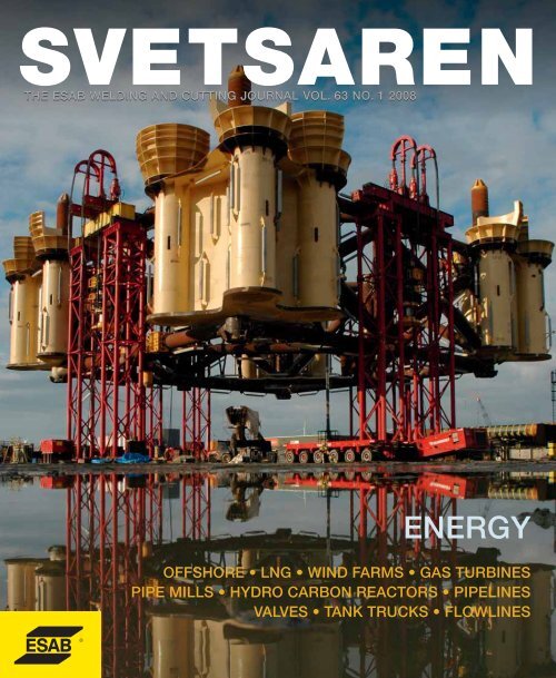
THE ESAB WELDING AND CUTTING JOURNAL VOL. 63 NO. 1 <strong>2008</strong><br />
ENERGY<br />
OFFSHORE • LNG • WIND FARMS • GAS TURBINES<br />
PIPE MILLS • HYDRO CARBON REACTORS • PIPELINES<br />
VALVES • TANK TRUCKS • FLOWLINES
Box Information.com<br />
Setting new standards<br />
We have now gained<br />
OHSAS 18001 group<br />
certification from DNV.<br />
Our group Environmental,<br />
Health & Safety<br />
Management System<br />
was already ISO14001<br />
certified. This is believed<br />
to be the most comprehensive<br />
certification<br />
achieved by any global<br />
company to date.<br />
It includes all production<br />
operations, sales and<br />
central functions within<br />
ESAB at 1 July 2007.<br />
Our system will benefit<br />
our customers<br />
It does not matter if our customers operate in China, Germany, US, Brazil<br />
or Sweden. Wherever in the world you buy ESAB products, these are<br />
produced in accordance with the same global EHS standards where<br />
occupational and product health & safety always comes first. Let us show<br />
you what a well managed company can do for you!<br />
www.esab.com
<strong>Svetsaren</strong><br />
ENERGY<br />
Articles in <strong>Svetsaren</strong> may be reproduced<br />
without permission, but with an<br />
acknowledgement to ESAB.<br />
Publisher<br />
Johan Elvander<br />
Editor<br />
Ben Altemühl<br />
Editorial committee<br />
Tony Anderson, Klaus Blome, Carl Bandhauer,<br />
Christophe Gregoir, Joakim Cahlin, Dan<br />
Erlandsson, Björn Torstensson,<br />
Nils Thalberg, Annika Tedeholm,<br />
José Roberto Domingues, Antonio Couto Plais.<br />
Address<br />
<strong>Svetsaren</strong><br />
ESAB AB Central Market Communications<br />
Box 8004<br />
S-402 77 Gothenburg<br />
Sweden<br />
Dear reader,<br />
Energy makes the world tick. Its generation and<br />
supply is a significant factor in global development,<br />
having an intimate effect on life style and quality. The<br />
lack of energy availability in many parts of the world,<br />
the growing awareness of the necessity to manage the<br />
limited resources and excessive and sometimes<br />
wasteful human behaviour, all create a challenge for<br />
the future.<br />
The limited availability of fossil fuels and their harmful<br />
effect on our environment, forces us to develop<br />
HARALD HESPE<br />
renewable forms of energy and, also, to explore the still<br />
enormous potential savings we can make in energy consumption. The latter is an integral<br />
element of ESAB’s environmental management system- rewarded with the ISO 14001<br />
global environmental certification.<br />
Our energy efficiency ratio in production sites and offices (revenues/energy use), for<br />
example, has doubled in 10 years (1996-2006) – as a result of focused and planned<br />
activities - and we intend to double this again in the coming decade. Another of our<br />
long- term strategic objectives is to significantly increase the use of energy from<br />
renewable sources (now 5%). This corporate policy guides our development efforts and<br />
demonstrates that leading industrial enterprises can take the initiative and can change<br />
traditional behaviour.<br />
Internet address<br />
http://www.esab.com<br />
E-mail: svetsaren@esab.com<br />
Printed in The Netherlands by True Colours<br />
The exploration of fossil fuel based resources has accelerated and taken on a new path<br />
in commercialising previously non-economic areas. Exploration takes place in more<br />
remote areas, more challenging environments in terms of climate and we are exposed to<br />
deep sea drilling and many more difficult engineering challenges. Wind power has<br />
become a global priority and we see renewed worldwide investment in nuclear power<br />
generation.<br />
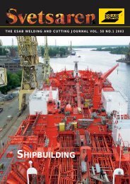
THE ESAB WELDING AND CUTTING JOURNAL VOL. 63 NO. 1 <strong>2008</strong><br />
Lifting of the<br />
Tombua Landana<br />
platform template<br />
at Heerema,<br />
Vlissingen,<br />
The Netherlands.<br />
This issue of <strong>Svetsaren</strong> features articles and application stories that illustrate the success<br />
of our clients and the deep involvement of ESAB as a welding and cutting solution<br />
provider for the energy generating industry.<br />
Good reading,<br />
ENERGY<br />
OFFSHORE • LNG • WIND FARMS • GAS TURBINES<br />
PIPE MILLS • HYDRO CARBON REACTORS • PIPELINES<br />
VALVES • TANK TRUCKS • FLOWLINES<br />
HARALD HESPE<br />
MANAGING DIRECTOR ESAB MIDDLE EAST FZE
Excellence in wind<br />
tower welding<br />
Competitiveness in wind tower fabrication<br />
is synonymous with the application<br />
of productive, high quality welding<br />
solutions. With ESAB, you are assured of a<br />
partner who understands your challenges<br />
and responds with innovative welding and<br />
cutting technology.<br />
We design and retrofit column & boom<br />
stations for submerged arc welding of<br />
circumferential and longitudinal<br />
welds – including head and tailstock,<br />
automation and integration in existing<br />
production lines. These are complemented<br />
by welding tractors and equipment for<br />
special components.<br />
Tandem - twin technology is our latest<br />
development in multi-wire welding heads<br />
providing unsurpassed deposition rates<br />
and welding productivity.<br />
Developed specifically for your industry,<br />
our flux/wire combinations ensure the<br />
required weld quality and mechanical<br />
properties - be it for land-based, offshore<br />
or even arctic wind towers.<br />
Visit us at www.esab.com
Contents<br />
07<br />
15<br />
18<br />
23<br />
26<br />
32<br />
34<br />
37<br />
Template for monster platform challenges<br />
Heerema.<br />
ESAB low-hydrogen consumable technology<br />
crucial in safe and productive welding.<br />
Port of Marseille sees LNG storage tanks<br />
erected with ESAB welding technology.<br />
Project, awarded to a joint venture of<br />
Saipem and Sofregaz, sub-contracted to<br />
the Italian Bentini Group SpA.<br />
SIF Group bv at the foundation of Dutch<br />
wind energy<br />
ESAB SAW technology crucial in the<br />
production of piles and transition pieces<br />
for the Q7 North Sea wind farm.<br />
Zorya-Mashproekt relies on ESAB for arc<br />
welding of gas turbine components<br />
Zorya-Mashproekt is a leading Ukranian<br />
producer of industrial and marine gas<br />
turbine power plants and engines.<br />
Complete and reliable partner for pipe mills.<br />
The latest ESAB equipment and consumables<br />
for longitudinal welding.<br />
Paresa SpA construct spheres for the<br />
Kuwait petrochemical industry<br />
Part of integrated petrochemical plant for<br />
hydrocarbons processing.<br />
ESW Inconel strip cladding<br />
Solution to clad steel shortage for<br />
Maritime Industrial Services, Dubai.<br />
Mechanised pipeline welding in the<br />
Saudi desert<br />
Magnatech orbital welding system and<br />
ESAB cored wire do the job.<br />
41<br />
43<br />
47<br />
51<br />
Cladding of valves for petrochemical<br />
plants.<br />
Valve manufacture and repair is a growth<br />
industry.<br />
Techint and ESAB Brazil - partners in the<br />
construction of the PRA-1 jacket.<br />
Technical partnership fundamental to the<br />
success of the project.<br />
Manufacture of mobile gasoline tanks in<br />
AlMg5 alloy at ZAO BECEMA, Russia.<br />
ESAB assists in conversion from steel to<br />
aluminium.<br />
Belleli Energy SpA reactors at the heart of<br />
Qatar’s Pearl Gas-to-Liquids Plant.<br />
ESAB arc welding consumables deliver<br />
quality and productivity.<br />
High integrity flowline welding at LMI<br />
56 ESAB orbital TIG technology crucial.<br />
58<br />
Product News<br />
• New power sources for orbital welding<br />
• Robust and powerful MIG/MAG Power<br />
sources for heavy duty welding<br />
• Caddy - the portable solution for<br />
professional welding<br />
• New Origo welding machine for<br />
demanding applications<br />
• Reactive welding helmets<br />
• AUTOREX – The first, totally encapsulated,<br />
automatic plasma cutting centre<br />
• Tramtrac TM II – flexible solution for the<br />
repair of embedded city tramway rails.<br />
• New submerged arc fluxes<br />
• OK Tubrod 14.11 – Metal cored wire<br />
for high speed thin plate welding<br />
• VacPac gets slimmer
6 - <strong>Svetsaren</strong> no. 1 - <strong>2008</strong>
Template for monster platform<br />
challenges Heerema.<br />
ESAB low-hydrogen consumable technology crucial in safe<br />
and productive welding.<br />
ALFRED VAN AARTSEN, HEEREMA VLISSINGEN B.V., THE NETHERLANDS AND ERIC DE MAN, ESAB NEDERLAND B.V., AMERSFOORT, THE NETHERLANDS.<br />
Thicker and heavier, and with<br />
sharper tolerances than ever<br />
before – this was in essence the<br />
challenge Heerema Vlissingen<br />
faced in the construction of the<br />
template for the Tombua Landana<br />
oil and gas platform. The answer<br />
was found in smart logistics and<br />
precision work, supported by<br />
proven welding solutions. (See<br />
page 14 for a description of the<br />
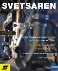
Figure 1. The tower base template TBT (grey), the tower bottom section TBS (brown) and the foundation piles.<br />
Tombua Landana project).<br />
Acknowledgement<br />
We thank Heerema Production Manager, Harm<br />
Sanstra, for facilitating our visits to the Vlissingen yard.<br />
Heerema Fabrication Group (HFG)<br />
Heerema is a name that requires little explanation<br />
– especially not for <strong>Svetsaren</strong> readers in the oil<br />
and gas industry. It is one of the bigger, globally<br />
operating players in the engineering and fabrication<br />
of large and complex structures for the oil<br />
and gas industry. It has been active in the<br />
offshore industry ever since oil and gas were<br />
discovered in the North Sea in the early 1960’s<br />
and enjoys a reputation for state-of-the-art<br />
engineering, fabrication and project management.<br />
HFG has yards in the Netherlands (Vlissingen and<br />
Zwijndrecht) and in the United Kingdom<br />
<strong>Svetsaren</strong> no. 1 - <strong>2008</strong> - 7
(Hartlepool). All are equipped with large prefabrication<br />
and assembly halls for indoor<br />
construction and are capable of handling large<br />
projects, simultaneously.<br />
HFG is part of the Heerema Group, together with<br />
Heerema Marine Contractors (HMC) which transports,<br />
installs and removes offshore facilities, and<br />
INTEC engineering, which provides engineering<br />
services to the energy industry. HFG Engineering,<br />
a subsidiary of HFG with offices in New Orleans<br />
and Houston, specialises in on- and offshore<br />
facility designs.<br />
All Heerema companies operate an integrated<br />
management system that complies with ISO 9001:<br />
2000 (Quality Management Systems), ISO 14001:<br />
2004 (Environmental Management System) and<br />
OHSAS 18001: 1999 (Occupational Health and<br />
Safety Management System) standards.<br />
The Tombua Landana template<br />
The tower base template (TBT) has a surface area<br />
of forty by forty metres, is 24 metres high and<br />
weighs 3,000 tons. It includes 12 main foundation<br />
piles with a total weight of 9,500 tons. It was completed<br />
and shipped to Angola in December 2007.<br />
Figure 1 shows a sketch of the TBT. The principal<br />
components are the pile sleeve clusters, the rows<br />
and the leveling jacks. Not indicated, but<br />
discussed later in this article, are the lifting<br />
trunnions – used for dual crane lifting with one of<br />
HMC’s specialised barges.<br />
The pile sleeve clusters form the cornerstones of<br />
the TBT. They guide the twelve foundation piles<br />
which are driven through them into the sea bed.<br />
Crucial during installation of the 190 m long piles in<br />
nearly 400 m deep waters, are the open cones on<br />
top of the pile sleeves. They catch the foundation<br />
piles hanging from the crane and guide them into<br />
the sleeves, after which pile driving commences.<br />
Part of the length of all foundation piles remains<br />
extended above the pile sleeves. The Tower Base<br />
Section – the lower part of the tower – is placed<br />
over them and secured to the template.<br />
The rows are a network of heavy pipes connecting<br />
the four pile sleeve clusters to form a rigid<br />
construction. Four leveling jacks, devices to<br />
position the template horizontally with great<br />
accuracy, are attached to the central columns of<br />
the rows. The shim piles on the leveling jacks rest<br />
on leveling piles in the sea bed. Leveling is<br />
performed by jacking the template up or down<br />
relative to the shim piles.<br />
The entire Tombua Landana project is characterised<br />
by very narrow construction tolerances, the<br />
substructures being placed on top of each other,<br />
in nearly 400 m deep waters - a particularly<br />
unforgiving environment for any misalignment.<br />
Also, the TBT was subject to strict dimensional<br />
tolerances – up to three times more precise than<br />
normally required in offshore fabrication.<br />
Moreover, it was the first part of the tower and all<br />
eyes were focused on Heerema. Two Daewoo<br />
representatives and two representatives of<br />
Chevron supervised the project and carried out<br />
regular inspections.<br />
Table 1. Mechanical requirements WPQ for type I and II steels.<br />
Steel grades, mechanical requirements and<br />
preheat temperatures<br />
Steel grades were purchased according to the<br />
“General Specification 1.14 Structural steels and<br />
other materials”, issued by the Cabinda Gulf Oil<br />
Company for the projects in block 14. In this<br />
specification, material types are ranked I and I-X,<br />
II and II-X, III, IV and V. Material types I are for structural<br />
members and tubular joint cans which are<br />
fracture critical and material types II are for structural<br />
members and cans where failure would pose a<br />
threat to the structure. Material types III, IV and V<br />
are for non-critical components. A list of valid steel<br />
classifications is given for each material type.<br />
Heerema Vlissingen purchased various types of<br />
plate according to EN 10225 Grade 355 (thermomechanically<br />
controlled rolled) and API 2MT1 as<br />
rolled, covering the demands of material types<br />
I and II, and meeting special constructional<br />
requirements such as “through thickness<br />
properties”. All main steel was purchased from<br />
Dillinger Hüttewerke in Germany.<br />
Mechanical weld requirements are established by<br />
Cabinda’s General Specification 1.15 – Structural<br />
welding and inspection. Charpy V-notch impact<br />
testing of both weld metal and heat affected zone<br />
was required on all welding procedure qualifications,<br />
with notch locations at the weld centre line, fusion<br />
line and FL+2mm. CTOD testing of the WM and<br />
HAZ was required for type I and II steels with a<br />
thickness greater than or equal to 63 mm (2.5”),<br />
to be performed on the thickest steel to be<br />
welded while using the highest preheat and<br />
interpass temperature permitted by the welding<br />
procedure to be qualified.<br />
Table 1 gives an overview of CVN and CTOD<br />
requirements. An additional cross weld zone hardness<br />
requirement was set at HV10 325 maximum.<br />
In constructions such as these, involving thick<br />
material, the prevention of hydrogen induced<br />
cracking (cold cracking) is essential. This starts<br />
with the purchase of steels with limited<br />
hardenability. Cabinda’s General Specification<br />
1.14 for structural steels and other materials<br />
therefore specifies a maximum Pcm value of 0.23<br />
(extended CE formula).<br />
In welding, preheating, along with the use of<br />
low-hydrogen consumables, is essential in the<br />
prevention of cold cracking. Cabinda General<br />
Specification 1.15 refers to AWS D1.1, for<br />
preheat and interpass temperatures to be applied.<br />
CVN<br />
CTOD<br />
Steel type minimum average minimum single thickness minimum<br />
I 34J/-40ºC 27J/-40ºC 76mm (3”)<br />
0.38mm/-10ºC<br />
II 34J/-18ºC 27J/-18ºC 76mm (3”)<br />
0.38mm/-10ºC<br />
8 - <strong>Svetsaren</strong> no. 1 - <strong>2008</strong>
Table 2. Preheat and interpass procedure.<br />
Thickness Preheat Interpass<br />
good CVN properties down to -60°C and is<br />
CTOD tested in the AW and SR condition. It has<br />
a vast track record that dates back to the years<br />
when MMA was the standard for manual welding<br />
in offshore fabrication. FILARC 76S is low-hydrogen<br />
with low moisture absorption properties. It is<br />
supplied to Heerema Vlissingen in VacPac vacuum<br />
packaging for ultimate protection.<br />
Table 3. Overview of low-hydrogen consumables used for the Tombua Landana template.<br />
ESAB consumables EN classification AWS Classification<br />
FILARC PZ6125 758: T 42 6 1Ni B M 1H5 5.29: E71T-5G<br />
FILARC PZ6138 758: T 46 5 1 Ni P M 1 H5 5.29: E81T1-Ni1MJ H4<br />
OK Flux 10.47/ OK Tubrod 15.24S EN: S 46 5 AB T3Ni1 (AW) 5.23: F8A4-EC-G (AW)<br />
FILARC 76S 499: E 42 6 Mn1Ni B 32 H5 5.5: E7018-G<br />
Major welding applications in the<br />
pile sleeve cluster<br />
Figure 3 shows the fabrication of a pile sleeve<br />
cluster. Its main components are indicated. The<br />
pile sleeve - the part which guides the foundation<br />
piles - has been pre-fabricated by Sif Group bv, in<br />
Roermond, along with the foundation piles themselves.<br />
Also the parts of the conical “pile catcher”<br />
allowing the use of SAW - mostly circumferential<br />
welds - are already attached during pre-fabrication.<br />
Heerema Vlissingen completes the catchers with<br />
stiffener plates (Figure 4). This involves a vast<br />
amount of full penetration butt welds, as well as<br />
fillet welds, all performed with manual FCAW, using<br />
FILARC PZ6138. Where possible, root passes are<br />
deposited on ceramic weld metal support.<br />
The welds connecting the pile sleeve to the shear<br />
plate involve a symmetrical double-sided K-joint in<br />
51 mm thickness (openings angle 40 degrees,<br />
root gap 5mm, root face 1mm), welded with the<br />
SAW process, using the OK Flux 10.47/OK<br />
Tubrod 15.24S flux/wire combination and ESAB<br />
A2 welding tractors. The root pass of these full-penetration<br />
welds is done with PZ6125, on ceramic<br />
backing, whereas sufficient thickness for the SAW<br />
process is obtained by a hot pass with PZ6138. In<br />
this stage, the construction can still be turned on<br />
roller beds, aided by contra weights, in order to use<br />
the productive SAW process on both sides.<br />
Turning the construction is no longer possible<br />
when two pile sleeve-shear plate pairs – grit<br />
pile sleeve<br />
catcher<br />
shear plate<br />
lower yoke plate<br />
upper yoke plate<br />
main leg<br />
Figure 3. Fabrication of a pile sleeve cluster.<br />
10 - <strong>Svetsaren</strong> no. 1 - <strong>2008</strong>
Figure 4. FCAW of the sleeves – the part that catches<br />
the foundation pile.<br />
Figure 5. Submerged arc welding of a sheer plate onto<br />
a pile sleeve.<br />
Figure 6. Lay-out of a row on the factory floor before<br />
welding – a precision job.<br />
blasted and painted - are connected to the main<br />
leg. Here a combination of SAW for the downhand<br />
side and FCAW for the overhead side is<br />
used (root FCAW on backing). The preparation is a<br />
2/3 –1/3 K-joint, so that the larger part of the joint<br />
volume can be welded in the downhand position<br />
with the productive SAW process. The 1/3 side is<br />
completed in the overhead position, using<br />
FILARC PZ6138 rutile cored-wire.<br />
When the shear plate of the third, and last pile<br />
sleeve in a cluster, is connected to the main leg,<br />
the joint position is horizontal-vertical. The joint<br />
preparation is again a symmetrical K-joint welded<br />
completely with the FCAW process, using FILARC<br />
PZ6138.<br />
The upper and lower yoke plates are connected<br />
by means of manual FCAW. It concerns full<br />
penetration X- and K-welds with all welding<br />
positions occurring. Again PZ6138 is the main<br />
consumable (roots on ceramic backing).<br />
TKY-joints in rows<br />
The rows - a network of heavy pipes connecting<br />
the four pile sleeve clusters – are pre-fabricated<br />
both indoors and outdoors. Their lay-out on the<br />
factory floor (Figure 6 ) exemplifies the great<br />
dimensional precision required.<br />
The two columns on the left and right are not part<br />
of the structure. They have the same dimensions<br />
as the main legs of the pile sleeve clusters and<br />
precisely set the dimensions of the row, before<br />
(tack) welding. Permittable deviations here are as<br />
narrow as ± 1/4” (6 mm) horizontally and<br />
± 1/8” (3 mm) vertically, requiring extreme<br />
accuracy. It is a procedure of virtually endless<br />
dimensional control. The same procedure is<br />
repeated during erection of the template<br />
(Figure 7), before rows are finally connected to the<br />
legs in the pile sleeve clusters.<br />
Figure 7. Erection of the template. All rows are first carefully positioned within the tolerances – with the help of temporary<br />
columns (left) – before they are attached to the docking pins in the pile sleeve cluster (cluster visible in the background).<br />
All nodes (TKY-joints) are welded in the positions<br />
as they occur in figure 7 with FCAW using PZ6125<br />
for the root and PZ6138 for filling. Figure 8 shows<br />
the FCAW welding on a special TKY-joint – the<br />
lifting trunniuns. These are used to attach the lifting<br />
cables onto the template during installation. Part of<br />
it is welded with SAW with OK Flux 10.47/OK<br />
Tubrod 15.24S (Figure 9).<br />
<strong>Svetsaren</strong> no. 1 - <strong>2008</strong> - 11
Figure 8. FCAW of a lifting trunnion.<br />
Figure 9. SAW on a lifting trunnion.<br />
Foundation piles<br />
The foundation piles are pre-fabricated by Sif<br />
Group bv, arriving in 83-93 m lengths. To achieve<br />
their final length of 170 –190 m, they need to be<br />
welded together (Figure 10 and 11). This is again<br />
done by FCAW with PZ6138, but here it is<br />
mechanised welding with ESAB Railtrac equipment.<br />
The joint configuration is adapted to this<br />
method -an unsymmetrical X-joint with most of<br />
the weld volume on the outside. The inside part is<br />
welded manually, vertically-up. The root pass is<br />
deposited on ceramic backing. After removal of<br />
the fit-up plates, the majority of the weld volume<br />
is mechanised welded from the outside, verticallyup<br />
from 6 to 12 ‘o clock, mostly with a slight<br />
weaving motion. Welding parameters are adapted<br />
to the several clock positions by the operators.<br />
Dimensional control and weld finish<br />
Normal offshore fabrication, eg, a jacket on top of<br />
which the deck and operational facilities are placed,<br />
is naturally, subject to strict dimensions, but it is<br />
more forgiving than in the case of the Tombua<br />
Landana project. The fact is that three<br />
substructures, fabricated by three different yards,<br />
are stacked on top of each other in almost 400 m<br />
deep waters - and simply have to fit. This places<br />
extremely high demands on the dimensional control<br />
– roughly 3 times as high as normally required.<br />
This is as equally valid for the fabrication of the<br />
TBT’s components – the pile sleeve clusters and<br />
the rows – as it is for the assembly of the super<br />
structure. To exemplify the dimensional control<br />
and its implications for welding, we return to the<br />
fabrication of the pile sleeve clusters, shown in<br />
Figure 12.<br />
This image shows the completed pile sleeve cluster<br />
and the nominal distances between the centre<br />
lines of the pile sleeves and the centre line of the<br />
main leg (5172.5 and 5173 mm). The maximum<br />
acceptable tolerance on these distances is 3 mm.<br />
A similar small tolerance is valid on the distances<br />
between the pile sleeves themselves, in the X and<br />
Y directions and on the mutual distances into the<br />
Z direction. This dimensional control is the key<br />
requirement, and everything else is subject to it.<br />
Ideally, the pre-fabricated yoke plates, including<br />
K-bevel, fit exactly, so that there is a constant<br />
root gap between the pile sleeves/main leg and<br />
Figure 10. Welding tents made from shrink foil protect the weld area from wind and rain.<br />
the yoke plate’s K-bevel. In practice, this is<br />
extremely difficult to achieve. Practically always, the<br />
root gap appears to be more or less eccentric. This<br />
must be corrected by grinding on the narrow side<br />
and buttering & grinding on the wider side<br />
– an extremely time consuming exercise.<br />
Measuring was performed by three parties;<br />
Heerema Vlissingen, Passe-Partout (independent<br />
contractor) and Chevron, who worked<br />
independently according to agreed measuring<br />
principles. Chevron were responsible for final<br />
measuring and reporting.<br />
Another time-consuming aspect was Class C and<br />
Class A grinding of weld surfaces. Grinding is<br />
done with an aluminium oxide based disc.<br />
Class C grinding is required for the TKY joints<br />
between the braces and the dummy leg (middle<br />
of the row) and between the braces and the main<br />
leg of the pile sleeve cluster. It is performed to<br />
correct excessive convexity, notches or undercut<br />
at the toes of the weld. The grinding of the toes<br />
of the cap must be performed to the point where<br />
a 1 mm diameter wire cannot pass between the<br />
disc and the plate (Figure 13).<br />
Class A grinding is performed on the welds connecting<br />
the lower yoke plates to the main legs of<br />
the pile sleeve clusters – at both sides of the<br />
K-joint. Class A means that weld profile is ground<br />
back to the theoretical radius. This is checked by<br />
using a template with a 45 mm radius, with a gap<br />
12 - <strong>Svetsaren</strong> no. 1 - <strong>2008</strong>
Figure 11. Vertically-up welding with ESAB Railtrac and<br />
FILARC PZ6138.<br />
Figure 12. Pile sleeve cluster dimensional control.<br />
the size of a paperclip not being allowed. The<br />
total length to be ground per weld was 2 x 11.5<br />
m for each of the four main legs.<br />
ISO 9001 and ISO 14001 approved world-wide.<br />
OHSAS 18001 is the latest approval obtained by<br />
ESAB, see page 2.<br />
Conclusion<br />
The Tombua Landana template was one of the<br />
most challenging projects ever undertaken by<br />
Heerema Vlissingen. It required a carefully<br />
planned factory lay-out and a level of precision<br />
not before experienced. The company finished<br />
the project within the agreed delivery term and,<br />
by the publication date of this <strong>Svetsaren</strong>, its sister<br />
company, HMC, will be involved in sea<br />
transportation and installation of the 474 m tall<br />
Tombua Landana oil and gas platform.<br />
The final words of this article should be<br />
addressed to the welders of Heerema Vlissingen<br />
who did such a tremendous job, notwithstanding<br />
the high preheat and interpass temperatures and<br />
overall tough working conditions.<br />
Figure 13. Class C grinding on TKY-joints to correct<br />
convexity, notches or undercut at the toes of the weld.<br />
Safety was essential. To step up its performance<br />
beyond already tough levels, Heerema Vlissingen<br />
took part in Chevron’s safety programme<br />
– Incident and Injury Free (IIF) – in which Chevron<br />
gave workshops and training to the yard personnel<br />
aiming at individual development.<br />
For its welding solutions, Heerema Vlissingen<br />
relied on low-hydrogen consumable technology<br />
from ESAB – a supplier that meets Heerema<br />
Vlissingen’s demands in any respect, including<br />
quality management systems, environmental<br />
management systems and occupational<br />
management systems. Like Heerema, ESAB is<br />
ABOUT THE AUTHORS:<br />
ALFRED VAN AARTSEN, EWE, IS WELDING ENGINEER AT<br />
HEEREMA VLISSINGEN B.V., THE NETHERLANDS.<br />
ERIC DE MAN, EWE, IS PRODUCT MANAGER<br />
CONSUMABLES AND KEY ACCOUNT MANAGER AT<br />
ESAB B.V., AMERSFOORT, THE NETHERLANDS.<br />
<strong>Svetsaren</strong> no. 1 - <strong>2008</strong> - 13
Tombua Landana project<br />
This huge oil and gas platform is due to be operational by the third quarter of 2009 in the Tombua<br />
and Landana deep water development areas, off the coast of Angola. The main contractor is Daewoo<br />
Shipbuilding & Marine Engineering, on behalf of Cabinda Oil Company and its partners. It is the production<br />
centre in the development of the oil and gas reserves in block 14, in Angolan waters.<br />
The Tombua Landana development follows the installation of the Benguela Belize-platform, an integrated<br />
drilling and production platform for the development of the Benguela and Belize fields. It was the industry’s<br />
first application of compliant piled tower structural technology outside the Gulf of Mexico. At 512 m, it is<br />
among the world’s tallest man-made structures.<br />
The Tombua Landana project involves the construction of the drilling and production platform, a subsea<br />
centre of water injectors and producers and the installation and tie-in of two export pipelines that will<br />
connect the Tombua Landana drilling and production platform to the Benguela-Belize oil and gas pipeline<br />
transportation system.<br />
The Tombua Landana platform stands 474 m tall, nearly as high as her twin-sister in block 14. The<br />
platform engineering, fabrication and installation has been contracted to Daewoo Shipbuilding & Marine<br />
Engineering (DSME). DSME will build the the topside in Okpo, Korea and has subcontracted the tower top<br />
section (TTS) to Gulf Island Fabricators, the tower bottom section (TBS) to Gulf Marine Fabricators (USA);<br />
and the tower base template (TBT) to Heerema Vlissingen, The Netherlands.<br />
Transport of all substructures to Angola and installation has been subcontracted to Heerema Marine<br />
Contractors, a sister company of Heerema Vlissingen.<br />
Project Scope<br />
Landana North via<br />
Lobito Subsea<br />
Center C<br />
(3) Producers<br />
(3) Water Injectors<br />
18” TL OIL EXPORT<br />
PIPELINE<br />
Benguela Belize<br />
Platform<br />
14” TL GAS<br />
EXPORT PIPELINE<br />
16” BBLT GAS<br />
EXPORT PIPELINE<br />
T-L Drilling<br />
& Production<br />
Platform<br />
30 wells<br />
130 MBOPD Tombua South<br />
Subsea Center<br />
(6) Producers<br />
(4) Water Injectors<br />
Malongo<br />
Terminal<br />
East Kokongo<br />
Nemba<br />
T-L<br />
Project<br />
Scope<br />
Tower Top Section (TTS)<br />
6,700 t<br />
Images on project description page<br />
(+map to be added)<br />
Tower Bottom Section (TBS)<br />
29,200 t<br />
Tower Base Template (TBT)<br />
3,000 t<br />
Taipei 101<br />
1667ft (508m)<br />
Petronas Towers<br />
1483ft (452m)<br />
Wells Fargo<br />
994ft (303m)<br />
Bank of America<br />
781ft (238m)<br />
The Gherkin<br />
591ft (180m)<br />
Tombua Landana<br />
1554ft (474m)<br />
14 - <strong>Svetsaren</strong> no. 1 - <strong>2008</strong>
Port of Marseille sees LNG storage<br />
tanks erected with ESAB welding<br />
technology.<br />
BRUNO MALAGOLI, ESAB SPA., MESERO, ITALY.<br />
Gas de France completed the expansion of<br />
their LNG receiving and distribution terminal in<br />
Fos Cavaou, near Marseille, in mid-2007. The<br />
project, awarded to a joint venture of Saipem<br />
and Sofregaz, comprised the engineering,<br />
procurement and construction of the overall<br />
terminal facilities, including three 110,000m 3<br />
LNG storage tanks, sub-contracted to the<br />
Italian Bentini Group SpA. whom relied on<br />
ESAB LNG welding technology.<br />
The Bentini SpA Group<br />
Established in the 1950s, the Bentini Group SpA,<br />
based in Faenza, Italy, expanded rapidly during<br />
post-war reconstruction, operating abroad as<br />
from 1976, and enjoying continuous growth and<br />
diversification in the civil and industrial<br />
plant-engineering sector, both as a main and sub<br />
contractor. It has a turnover of 150 million Euros<br />
and over 1200 employees, operating in France,<br />
Algeria, Libya and Nigeria. In Algeria, it has two<br />
daughter companies; Gepco SpA, a general<br />
contractor in the oil and gas industry, and Benco<br />
SpA, a general construction contractor.<br />
LNG tanks<br />
The project consisted of three cryogenic tanks,<br />
each with a capacity 110,000m 3 . They are<br />
cylindrical in shape with a diameter of 80m and<br />
an overall height of 37m. The maximum liquid<br />
level inside the tank is 24m. The inner wall (in<br />
contact with the liquid gas) is constructed from<br />
X8Ni9 steel (EN 10028-4) - a 9% nickel steel,<br />
<strong>Svetsaren</strong> no. 1 - <strong>2008</strong> - 15
typically for cryogenic applications down to<br />
-196°C. Here the liquefied natural gas, arriving in<br />
LNG tankers, is stored and held at a temperature<br />
of -163°C at a pressure slightly above atmospheric.<br />
For distribution, the LNG is re-gasified by heat<br />
exchange with sea water, odorised and transported<br />
through the pipeline network at a pressure of<br />
70-100 bar.<br />
The thickness of the tank bottom plates is 6mm,<br />
and the stringer plate 10mm. The metal plates for<br />
the primary tank - in contact with the liquid - vary<br />
in thickness from 16.6mm (at the bottom) to<br />
12mm (at the top), compensating for the<br />
hydrostatic pressure from the stored liquid, which<br />
increases gradually towards the bottom. Figure 1,<br />
representing the tank cross section, gives an idea<br />
of the complexity and types of materials involved<br />
in the construction.<br />
Materials and welding<br />
The main component is the primary tank<br />
designed to contain the liquid natural gas. The<br />
primary tank is surrounded by a corner protection<br />
system - lower in height and designed to offer<br />
additional safety in the case of liquid leakage from<br />
the primary tank. These components are made<br />
from 9%Ni steel, resistant to temperatures down<br />
to -196°C (coloured red in Figure 1). Further protection,<br />
known as the vapour barrier and covering<br />
the whole tank internally, is made of carbon steel<br />
plates and serves to hold the gas in equilibrium<br />
with the liquid.<br />
According to Bentini’s Welding Engineer in<br />
charge, Mr. Emanuele Ceroni, “The welding was<br />
of vital importance – from the initial welding<br />
process qualifications right through to the on-site<br />
management and monitoring of the human<br />
resources - due to the importance of the<br />
construction and the potentially associated risks.<br />
The welding processes used for construction of<br />
the tank are MMA, SAW and semi-automatic<br />
GMAW. The latter process was used for welding<br />
the suspended aluminium roof with ESAB OK<br />
Autrod 5183 wire. For the vertical joints of the<br />
carbon steel vapour barrier, about 7500m for<br />
each tank, Saipem had proposed uphill MMA.<br />
The two phases in construction of the suspended<br />
roof and vapour barrier did not overlap. I, therefore,<br />
had the idea to also use the semi-automatic<br />
Figure 1. Cross section of the LNG storage tank.<br />
GMAW process for the vapour barrier, where it<br />
involved a fillet weld. After obtaining approval from<br />
Saipem we searched for the right consumable.<br />
ESAB advised us to use the vertical downhill<br />
technique with 1.2mm diameter Tubrod 14.12<br />
wire. In production, this wire allows an appreciable<br />
increase in productivity and consequent saving of<br />
time, as well as limited deformation.”<br />
As previously mentioned, various materials are<br />
involved in the construction, starting with the<br />
most strategic component, X8Ni9 steel (EN<br />
10028-4), with 9% nickel. It is steel typically used<br />
for cryogenic applications and has been widely<br />
used in this type of plant. However, as it is highly<br />
sensitive to magnetic fields, it could create<br />
potential problems associated with welding. This is<br />
the reason why the ESAB OK 92.55 electrode was<br />
chosen as it can also be used with AC to minimise<br />
the risk of magnetic arc blow. Most of the welding<br />
of the 9% nickel steel was done with these electrodes<br />
at a consumption of around 32 tons.<br />
1 – Piping from 114.3 to 762.0mm<br />
(mat. EN 10028-7 X2CrNi 18/9)<br />
2 – Compression ring<br />
(mat. EN 10028-3 P 355 NL1)<br />
3 – Outer reinforced concrete wall<br />
4 – Carbon steel vapour barrier<br />
(mat. EN 10028-3 P 275 NL1)<br />
5 – Main tank (mat. EN 10028-4 X8Ni9)<br />
6 – Insulation with perlite<br />
7 – Corner protection system<br />
(mat. EN 10028-4 X8Ni9)<br />
8 – Resilient blanket<br />
9 – Bottom, carbon steel vapour barrier<br />
(mat. EN 10028-3 P 275 NL1)<br />
10 – Bottom, secondary tank<br />
(mat. EN 10028-4 X8Ni9)<br />
11 – Bottom, primary tank<br />
(mat. EN 10028-4 X8Ni9)<br />
12 – Foundation<br />
13 – Suspended aluminium roof<br />
(mat. ASTM B 209 ALLOY 5083)<br />
14 – Stringer plate<br />
(mat. EN 10028-4 X8Ni9)<br />
A smaller quantity of wire and flux was used for<br />
submerged arc welding of the bottom plate with a<br />
suitable tractor and for circumferential welding<br />
with the ESAB Circomatic system, using<br />
ERNiCrMo-4 wire.<br />
In construction, carbon steel was used for the<br />
metal plates of the outer lining, P275NL1 steel<br />
(EN 10028-3) for the base and S 275 J2G3 (EN<br />
10025) for the entire roof structure. Also, part of<br />
the piping was made of ASTM A106 Gr. B steel.<br />
A total of 21 tons of ESAB Citobasico electrodes,<br />
2600kg of ESAB OK Tubrod 14.12 cored wire<br />
and modest quantities of OK Tigrod 12.60 for<br />
certain TIG welding operations were used.<br />
In addition, a high quantity of stainless steel<br />
piping in X2CrNi 18/9 (EN 10028-7) was welded<br />
with ESAB OK 61.35. ESAB OK 67.60 (309L)<br />
electrodes were used for the dissimilar joints<br />
between stainless steel and carbon steel, as well<br />
as for the joints between pipes and metal plates<br />
16 - <strong>Svetsaren</strong> no. 1 - <strong>2008</strong>
of the roof, involving an overall consumption of<br />
approximately 7-8000kg, in addition to 1400kg of<br />
ESAB OK Tigrod 16.10 rods.<br />
Finally, the suspended aluminium roof (Figure 1),<br />
made of ASTM B209 alloy 5083, was welded<br />
with the GMAW process using 1.2mm and<br />
2.4mm ESAB OK Autrod 5183 wire, total<br />
consumption being1500kg.<br />
Co-operation<br />
“Our relationship with ESAB is excellent”, says<br />
Emanuele Ceroni. “Throughout the project, we<br />
received full support in terms of presence,<br />
assistance, advice, competence and innovation,<br />
as in the case of the OK Tubrod 14.12 wire.<br />
ESAB lives up to its image in quality, supply<br />
and service.”<br />
ABOUT THE AUTHOR:<br />
NAAM BRUNO FUNCTIE. MALAGOLI IS PRODUCT MANAGER<br />
CONSUMABLES AT ESAB SPA., MESERO, ITALY.<br />
<strong>Svetsaren</strong> no. 1 - <strong>2008</strong> - 17
SIF Group bv at the foundation of<br />
Dutch wind energy<br />
ESAB SAW technology crucial in the production of piles and<br />
transition pieces for the Q7 North Sea wind farm.<br />
ERIC DE MAN ESAB NEDERLAND B.V. THE NETHERLANDS AND WILLIAM LAFLEUR SIF GROUP BV THE NETHERLANDS<br />
Q7 is the largest offshore wind farm<br />
in the Dutch sector of the North Sea<br />
and a step forward in the<br />
Netherlands’ renewable energy<br />
policy to boost wind energy<br />
production to 2750 MW by 2020.<br />
Sif Group bv manufactured the<br />
foundation piles and the transition<br />
pieces.<br />
Source: Offshore Windpark Q7<br />
18 - <strong>Svetsaren</strong> no. 1 - <strong>2008</strong>
Figure 1. One of the monopiles being driven into the sea bed. The piles are 50 or 54 m in length and the water<br />
depth is 19-24 m. Source: Offshore Windpark Q7.<br />
Figure 2. Positioning of a transition piece onto a monopile.<br />
The transition piece reaches 15 m above sea level.<br />
Acknowledgement.<br />
We thank the management of Sif Group bv for<br />
facilitating our visit to the production site.<br />
The Q7 project<br />
The Q7 offshore wind farm has been built some<br />
23 km offshore from IJmuiden, in block Q7 of the<br />
Dutch continental shelf. It is unique in the sense<br />
that it is the world’s first located at such a distance<br />
from the coast (outside the 12-mile zone)<br />
and in deeper waters than ever before (19-24m).<br />
This was one of the reasons why its owners,<br />
sustainable energy group Econcern, and energy<br />
company ENECO Energie, selected the proven<br />
technology of the Vestas V-80 2.0 MW turbines.<br />
The project comprises 60 wind turbines with a<br />
total capacity of 120 MW.<br />
Under the Kyoto Protocol, The Netherlands<br />
agreed to reduce greenhouse gas emissions, in<br />
the period <strong>2008</strong>-2012, by 6% relative to the 1990<br />
levels. The Q7 project will contribute a reduction<br />
of 225,000 tonnes of CO 2<br />
emission, annualy.<br />
Van Oord, an international dredging and marine<br />
contractor, was responsible for the installation of<br />
the wind farm; offshore erections starting in May<br />
2007.<br />
The foundation piles (monopiles), 54 m long with a<br />
diameter of 4 m and 320 tons in weight, were<br />
driven into the sea-bed for over half their length.<br />
The transition pieces, weighing 115-tons and<br />
reaching 15 m above sea level, were placed onto<br />
the foundations using Jumping Jack, a<br />
specially designed vessel (Figures 1 & 2).<br />
The masts (105 tonnes), and the turbines (65<br />
tonnes), are produced by Vestas and shipped to<br />
IJmuiden for erection. Sea Energy – another<br />
dedicated offshore construction vessel<br />
– transported two wind towers and two turbines<br />
at a time to Q7 for installation.<br />
To minimise turbine interaction, guidelines<br />
stipulate that the turbines must be separated by a<br />
distance of at least 5 times their rotor diameter<br />
(5 x 80m). The Q7 turbines are placed apart at a<br />
distance of 550m.<br />
Van Oord was also responsible for the installation<br />
of a 520 ton transformer substation on a<br />
monopile in the middle of Q7 - the first offshore.<br />
Q7 will be fully operational in March <strong>2008</strong>.<br />
Sif Group bv<br />
Sif Group bv, located in Roermond, The<br />
Netherlands, specialises in the manufacture of<br />
heavy tubular structures for the offshore oil and<br />
gas industry, offshore windfarm foundations,<br />
harbour and jetty facilities, and pressure vessel<br />
shells and cones. The company has vast<br />
experience in welding, heat treatment and nondestructive<br />
and destructive testing of fine grained<br />
high strength structural steels commonly used in<br />
these industries. Sif Group bv is located on the<br />
river Maas with its own docking facilities and direct<br />
connections to strategically located main ports,<br />
such as Rotterdam and Antwerp, enabling them to<br />
ship structures of any dimension and weight, up to<br />
800 tons, using coasters or their own river barges.<br />
Anticipating the boom in offshore wind farms, Sif<br />
Group bv invested heavily in a new yard lay-out, a<br />
new production hall for foundation piles and<br />
<strong>Svetsaren</strong> no. 1 - <strong>2008</strong> - 19
(+ flange) and the monopiles. The design temperature<br />
of the transition piece was -10°C (above<br />
LAT - Lowest Anticipated Tide) and 0° (below<br />
LAT) for the monopiles, whereas the lowest CVN<br />
test temperature was -50°C, valid for the thickest<br />
wall sections of the transition pieces. The<br />
construction was subject to GL Rules &<br />
Regulations IV Part 2: Regulations for the<br />
certification of Offshore Wind Energy Conversion<br />
Systems Edition 1999.<br />
Figure 3. Monopile under construction. Note the longitudinal en circumferential welds.<br />
modern production lines - a process that is still<br />
ongoing. This policy has been extremely successful,<br />
judging by the impressive list of offshore wind<br />
farms in Western Europe in which the company<br />
has been involved. More than 80% of the installed<br />
offshore wind farms rely on steel foundations<br />
fabricated by Sif Group bv, amongst them the<br />
Horns Rev project in Denmark (the second largest<br />
farm to date) and the Q7 project.<br />
Sif Group bv maintains an effective quality<br />
management system certified in accordance with<br />
the ISO 9001: 2000 standard and with the<br />
implementation of EN-ISO 3834-2 comprehensive<br />
quality requirements for welding. Additional<br />
international approvals and authorisations include:<br />
• Structural tubulars: API Spec. 2B<br />
• Pressure vessel parts: ASME U stamp, ASME<br />
U2 stamp, ASME S stamp, PED 97/23<br />
• Dynamically loaded Steel Structures:<br />
DIN 18800-7 Class E – Ü stamp.<br />
Dimensions, material grades and mechanical<br />
requirements.<br />
The challenging Q7 project involved the manufacture<br />
of 61 mono piles and 61 transition pieces<br />
(60 for the wind farm and one for the transformer<br />
station). Both are tubular structures; the monopiles<br />
are straight and the transition pieces slightly conical.<br />
Figure 3 shows a monopile under construction.<br />
The principal weld connections, the longitudinal<br />
and circumferential welds are clearly visible. The<br />
individual cans are 3–3.5m in length and 4m in<br />
diameter with the longitudinal welds staggered at<br />
180° intervals from can to can. The wall thickness<br />
varies over the length of the monopile, from 45mm<br />
for the thinnest section, to 86mm. Transitions<br />
between differing wall thickness were smoothed by<br />
chamfering (1:5) and/or weld build-up.<br />
Table 1 gives an overview of steel grades and<br />
CVN impact requirements for the several thickness<br />
ranges, both for the transition pieces<br />
Sif fabrication of monopiles and transition<br />
pieces.<br />
The production line starts with beveling by flame cutting<br />
or machining and subsequent cold rolling of<br />
plates to a ring section. With two bending machines,<br />
Sif Group bv can roll plate with a thickness of<br />
20-150mm to shells with a diameter of 0.6 to 8m<br />
and a maximum width of 4.2m (Figure 4). The rolling<br />
process is performed in several steps to achieve the<br />
specified dimensions and roundness; also to facilitate<br />
perfect alignment for high productivity welding.<br />
Tubular structures, in general, and monopiles, in<br />
particular, are straightforward constructions with<br />
heavy longitudinal and circumferential welds. SAW<br />
makes up more than 90% of all welding. Serial<br />
production depends on an efficient factory lay-out<br />
where fabrication is performed in a logical<br />
sequence, minimizing internal transportation of<br />
components. Factory lay-out is also important to<br />
achieve the full production potential offered by the<br />
Table 1. Material grades, thickness and impact requirements<br />
Application Thickness Structural<br />
Category<br />
Material<br />
grade specified<br />
Test<br />
temperature<br />
Impact energy<br />
energy requirements<br />
Transition shell<br />
T< 45 primary S355J2G3- -30°C 34J av. (L)<br />
Td = -10°C<br />
EN10025<br />
24J av. (T)<br />
45
equipment and the welding heads getting<br />
jammed by weld metal shrink (longitudinal welds)<br />
Submerged arc welding<br />
Another constant factor is the wire/flux combination.<br />
Sif Group bv generally uses ESAB OK Autrod<br />
12.32 solid wire for medium and high strength<br />
steels (EN756: S3Si) combined with a high basic<br />
flux (EN760: SA FB 1 55 AC H5).<br />
The combination yields good impact properties<br />
down to -60° and is ideal for the various<br />
multi-wire SAW processes applied by Sif Group bv.<br />
Essential is the good slag release, mostly selfdetaching,<br />
in the first runs of the narrow gap joints.<br />
Figure 5. Semi-narrow gap joint used for external longitudinal<br />
and circumferential joints.<br />
Figure 4. Rolling plates to shells; the first fabrication step<br />
in the production of monopiles.<br />
submerged arc welding process.<br />
Joint preparation is basically the same for all<br />
welds, with only the semi-narrow gap varying in<br />
depth, dependent on the wall thickness. It is similar<br />
for all heavy tubular constructions produced by<br />
Sif Group bv, be it monopiles, foundation piles for<br />
oil rigs, jacket legs or other components for the oil<br />
and gas industry. It makes production predictable,<br />
ensures reproducible weld quality and reduces<br />
the start-up times from project to project.<br />
The semi-narrow gap joints produced through the<br />
milling process are geometrically exact, smooth,<br />
even, and burr-free, their quality surpassing that<br />
of back-gouged joints. Furthermore it has the<br />
advantage that the root of the internal welds can<br />
be taken out, together with any weld imperfections,<br />
in this critical area of the joint (Figure 5)<br />
Narrow gap welding, of course, has the<br />
advantage of a reduced weld volume and, thereby,<br />
a shorter welding time per joint and reduced weld<br />
metal consumption. The option for a semi-narrow<br />
gap, with an included angle of 13°, was made to<br />
avoid access problems for the multi wire SAW<br />
OK Autrod 12.32 is supplied on specially<br />
designed bulk spools with 350 or 700kg of wire<br />
– known as spiders - designed to fulfill the specific<br />
Sif Group demands and only supplied to them<br />
(Figure 6). They are colour-coded, separating<br />
them from occasional other wire qualities supplied<br />
on spider, and wrapped in a protective foil that<br />
can remain on the spools without hindering the<br />
wire pay-off. The wire is spooled to discharge in<br />
the direction needed for the multi-wire SAW<br />
systems. The specification of OK Autrod 12.32 is<br />
very narrow in regard to chemical composition<br />
and surface condition - to fulfill offshore<br />
requirements.<br />
The special production line for the manufacture of<br />
wind turbine foundations consists of several multiwire<br />
submerged arc welding stations, most<br />
equipped with ESAB welding components and<br />
high duty LAF/TAF power sources. Sometimes<br />
ESAB and Sif Group BV cooperate in retrofitting<br />
existing column and boom-type stations or the<br />
provision of complete new automatic solutions.<br />
A recent example was a customer-designed SAW<br />
installation for welding of internal stiffener rings in<br />
tubular constructions.<br />
The portal welders, where the larger piles are<br />
completed, are huge and highly efficient (Figure 8).<br />
Circumferential welds are simultaneously welded<br />
by an operator controlled multi-wire station, the<br />
deposition rates thus achieved being impressive.<br />
The system is equipped with PLC controls and<br />
optical sensors, which monitor and control the<br />
entire welding process and guarantee a consistent<br />
and high weld quality. The operator starts the<br />
Figure 6. OK Autrod 12.32 supplied on customer<br />
designed spindles.<br />
Figure 7. Macro of a typical weld cross section in 70mm<br />
plate.<br />
<strong>Svetsaren</strong> no. 1 - <strong>2008</strong> - 21
Table 2. Weld metal properties at -50°C in 70mm plate from a WPS comparable to the weld of figure 5.<br />
Cv-impact energy [J]<br />
Average<br />
1st welded side V-joint, SAW-twin 2 mm subsurface 111J 94J 90J 98J<br />
2nd welded side U-joint, SAW-triple 2 mm subsurface 110J 102J 104J 105J<br />
Root area 50 mm depth 112J 154J 150J 139J<br />
welding process manually and the system<br />
automatically completes the full welding sequence,<br />
including the positioning of split beads across the<br />
width of the joint. If necessary, the operator can<br />
change to manual control at any time.<br />
Figure 7 shows an example of an absolutely<br />
flawless heavy weld obtained in this manner. Weld<br />
metal properties at -50°C, from a related welding<br />
procedure qualification for Q7 in 70mm plate<br />
thickness, are given in table 2.<br />
Sif Group bv is particularly impressed with the<br />
performance of the ESAB wire feeders on the<br />
narrow gap equipment and the LAF 1250 and<br />
TAF 1250 power sources. The installation<br />
operates 24 hours a day, with minimal<br />
maintenance, and has not given a single problem<br />
over a period of 2 years.<br />
Figuur 8. Portal welder for circumferential welding, in operation.<br />
Sif Group bv Reference list of windfarm projects.<br />
• 1994 Medemblik, Netherlands 4 Monopiles Ø 3.500x35x28.000mm Weight 346 ton<br />
• 2002 Horns Rev, Denmark 80 Monopiles ø 4.000x50x58.000mm Weight 11.080 ton<br />
80 Transitions ø 4.240x35x15.000mm Weight 5.325 ton<br />
• 2003 North Hoyle, United Kingdom 30 Monopiles ø 4.000x30:70x58.000mm Weight 8.508 ton<br />
30 Transitions ø 4.200x35x12.300mm Weight 1.150 ton<br />
• 2003 Arklow, Ireland 7 Monopiles ø 5.000x50x45.000mm Weight 1.931 ton<br />
7 Transitions ø 5.390x45x15.150mm Weight 929 ton<br />
A bright future in wind energy<br />
By timely investment in new welding technology<br />
and production facilities, Sif Group bv has been<br />
able to gain a strong foothold in the Western<br />
European offshore wind energy market and made<br />
a major contribution to the generation of clean<br />
energy. The project list at the end of this article<br />
highlights the company’s reputation as a reliable<br />
partner for large wind energy projects. With many<br />
new wind energy projects anticipated, the future<br />
looks bright. Partnered with ESAB for welding<br />
technology, the company can be assured of a<br />
supplier that understands its needs and can<br />
respond to its specific requirements.<br />
• 2004 Kentish Flat, United Kingdom 30 Monopiles ø 4.300x50x37.000mm Weight 5.013 ton<br />
30 Transitions ø 4.540x35x12.050mm Weight 1.823 ton<br />
• 2005 Barrow, United Kingdom 30 Monopiles ø 4.750x45:75x51.000mm Weight 11.320 ton<br />
30 Transitions ø 5.100x55x21.600mm Weight 3.460 ton<br />
• 2006 Burbo, United Kingdom 25 Monopiles ø 4.700x45:75x37.000mm Weight 5.307 ton<br />
25 Transitions ø 5.390x45:67x22.350mm Weight 3.994 ton<br />
• 2006 Beatrice, United Kingdom 2 sets Central Pipe, Legs & Pilesleeves Weight 832 ton<br />
8 Piles ø 1.869x60/80x42.500mm Weight 935 ton<br />
• 2006 Onshore Tripod Multibrid, Germany 1 Main column ø 6.000x35:75x26.000mm Weight 203 ton<br />
3 Pileguides ø 2.900x40:65 x 9.000mm Weight 102 ton<br />
• 2006 Q7, The Netherlands 61 Monopiles ø 4.000x35:79x54.000mm Weight 18.700 ton<br />
61 Transitions ø 4.200x35:57x19.000mm Weight 5.340 ton<br />
• 2007 Lynn & Inner Dowsing, UK 54 Monopiles Ø 4.740x50/75x36.000mm Weight 12.100 ton<br />
54 Transitions Ø 5.100x45/67x22.050mm Weight 9.100 ton<br />
ABOUT THE AUTHORS:<br />
ERIC DE MAN, BSC, EWE, IS PRODUCT MANAGER<br />
CONSUMABLES AND KEY ACCOUNT MANAGER AT<br />
ESAB NEDERLAND B.V., AMERSFOORT, THE<br />
NETHERLANDS.<br />
WILLIAM LAFLEUR, BSC, EWE, IS MATERIAL &<br />
WELDING ENGINEER AT SIF GROUP BV, ROERMOND,<br />
THE NETHERLANDS.<br />
22 - <strong>Svetsaren</strong> no. 1 - <strong>2008</strong>
Zorya-Mashproekt relies on ESAB for<br />
arc welding of gas turbine components<br />
YURIY BUTENKO, SE RPCGTI ZORYA-MASHPROEKT, NIKOLAEV, UKRAINE AND ALEXEY BELIKOV, ESAB RUSSIA, MOSCOW, RUSSIA.<br />
The Zorya-Mashproekt Gas Turbine<br />
Building Research and Production<br />
Complex is a leading Ukranian producer<br />
of industrial gas turbines<br />
and marine gas turbine power<br />
plants and engines. Although,<br />
today, naval demand is far from<br />
exhausted, particular emphasis is<br />
placed on the production of civil<br />
equipment. In the wake of associated<br />
technical developments, the<br />
company recently invested in<br />
state-of-the-art ESAB arc welding<br />
systems.<br />
The Zorya-Mashproekt Gas Turbine Building<br />
Research and Production Complex was founded<br />
in the early 1950s in Nikolaev, Ukraine, for the<br />
development and production of gas turbine<br />
equipment and reducers for vessels of the USSR<br />
Navy. In the 1970s, the company was assigned to<br />
develop and manufacture gas turbines for use in<br />
compressor stations on trunk gas lines and in<br />
mobile and stationary power plants. Over more<br />
than half a century, Zorya-Mashproekt has produced<br />
four generations of gas-turbine engines,<br />
used in around 500 battleships and commercial<br />
vessels. Twenty-four power plants, with a total<br />
capacity of 1120 MW, and over 500 gas compressor<br />
units, with a total capacity of more than<br />
6000 MW, are equipped with the company’s gas<br />
turbines.<br />
Today, Zorya-Mashproekt products compete with<br />
leading fabricators around the world, the main<br />
products being engines based on the DO71,<br />
DO90 and DO80 gas turbines with a capacity of<br />
6, 16 and 25 MW respectively. A new engine,<br />
DN70, with a capacity of 10 MW and an efficiency<br />
of 35%, is under development. It will replace<br />
technically outdated and less efficient turbines.<br />
Another development, demanded by the power<br />
generation industry, is a one-shaft engine with a<br />
capacity of 45-60 MW.<br />
ESAB assessment and advice<br />
Various steels and alloys are used in modern gas<br />
turbines, for example, CMn steels, low-alloyed<br />
steels, austenitic and martensitic stainless steels,<br />
high-alloyed steels and nickel-base alloys. Some<br />
components are made of titanium (eg, turbine<br />
fans). When producing turbine parts, minimum<br />
weight and maximum material utilisation are<br />
Figure. 1. Zorya-Mashproekt’s DN-80 25MW gas turbine.<br />
<strong>Svetsaren</strong> no. 1 - <strong>2008</strong> - 23
Figure. 2. Welding with one of the automatic TIG stations.<br />
important factors. Most parts are manufactured<br />
using welding technologies and the welded joint<br />
is often the crucial element defining the operational<br />
capability of the part. Also, with the limited<br />
weldability of some of the materials used, the<br />
most important consideration for the welding<br />
specialist is the selection of the appropriate and<br />
most efficient welding process, equipment and<br />
consumables.<br />
Electron-beam welding is the principal welding<br />
process used in the fabrication of gas-turbine<br />
engines. It is performed under vacuum, which<br />
protects the weld pool and facilitates weld metal<br />
strength, deformation being minimal due to the<br />
highly concentrated heat source. However, for many<br />
components, arc welding processes are preferred.<br />
Co-operation with ESAB began in 1995, when<br />
company management set the task of increasing<br />
production output and reducing welding costs.<br />
ESAB specialists carried out a technical audit of<br />
the welding methods used in production. Its<br />
conclusion was that, without up-to-date arc<br />
welding technologies - MMA and manual TIG<br />
welding being the main arc welding processes –<br />
results were high weld metal consumption and<br />
unnecessarily low overall productivity.<br />
Also, repair rates were high because the superior<br />
weld quality standard was hard to meet - even by<br />
qualified welders.<br />
The audit resulted in a recommendation for<br />
investment in programmable automatic TIG<br />
systems, programmable pulse inverter power<br />
sources and the replacement of MMA welding by<br />
MIG/MAG and cored wire welding (FCAW),<br />
wherever possible. In response to this, Zorya-<br />
Mashproekt acquired two ESAB automatic TIG<br />
systems, consisting of a MKR-300 column &<br />
boom, A 25 TIG welding head and A2 Minimaster<br />
GMAW head, PEG1 control unit, AristoMig 500<br />
power source (today named AristoMig 5000i) and<br />
PEMA-1500 positioners. For manual welding, the<br />
company bought various AristoMig 500<br />
multi-process inverters with U8 control unit – one<br />
machine covering MMA, TIG, MIG/MAG and FCAW.<br />
Automatic TIG<br />
Automatic TIG welding is used for the circumferential<br />
and longitudinal welds in gas turbine<br />
bodies in 3-8 mm thick austenitic or martensitic<br />
stainless steel or nickel-base alloys. It involves<br />
pulsed TIG welding of I-joints without a root gap,<br />
onto a copper backing bar, and without filler<br />
material addition. Plate thicknesses up to 3 mm<br />
are welded one-sided and, above 3 mm, two-sided.<br />
Argon is both shielding and backing gas – the<br />
latter flowing into the root area through holes in<br />
the backing bar. Special devices ensure tight<br />
clamping of the weld edges onto the backing bar.<br />
Welding parameters and sequence are pre-programmed<br />
in the control unit, for the various materials<br />
and plate thicknesses. Table 1 gives an<br />
example of actual parameter settings and Figure<br />
3 shows a weld deposited with these parameters.<br />
This method has a number of advantages, in<br />
addition to a dramatic increase in productivity.<br />
By fully controlling the arc, the quality and<br />
Table 1. Parameters for automatic pulse TIG welding of<br />
steel (347) with 3 mm wall thickness.<br />
No Parameters of welding mode Value<br />
1. Pulse current, A 210<br />
2. Background current, A 40<br />
3. Pulse duration, sec. 0.40<br />
4. Inter-pulse time, sec. 0.42<br />
5. Upslope, sec. 0.1<br />
6. Downslope, sec. 0.8<br />
7. Gas pre-flow, sec. 1.0<br />
8. Gas post-flow, sec. 5.0<br />
9. Travel speed, cm/min 18<br />
10.<br />
Consumption of argon for gas<br />
shielding, l/min.<br />
11.<br />
Consumption of argon for gas<br />
backing, l/min.<br />
4<br />
12. Arc length, mm 2<br />
13.<br />
Diameter of tungsten electrode,<br />
mm.<br />
8<br />
4.0<br />
Table 2. Consumables classifications.<br />
EN<br />
SFA/AWS<br />
FILARC PZ6166 12073: T 13 4 M A5.9: EC410NiMo<br />
OK Tubrod 14.31 12073: T 19 12 3 L R M 3 A5.22: E316LT0-1, E316LT0-4<br />
OK 68.25 1600: E 13 4 B 4 2 A5.4: E410NiMo-15<br />
OK 63.30 1600: E 19 12 3 L R 12 A5.4: E316L-17<br />
Figure. 3. Appearance of a weld deposited by automatic TIG welding with the<br />
parameters of Table 1.<br />
24 - <strong>Svetsaren</strong> no. 1 - <strong>2008</strong>
25 ±2° 25 ±2°<br />
4 +1<br />
ring<br />
copper backing bar<br />
Figure 4. Joint preparation of a ring for the outlet part of<br />
a turbine.<br />
Figure 5. Flux-cored arc welding of an outlet ring, using FILARC PZ6166 and the AristoMig 500 inverter power source.<br />
appearance of the weld become consistent and<br />
repeatable. Also, the lower heat input from pulse<br />
welding gives lower welding stresses and<br />
consequently lower deformation, as well as a<br />
reduced risk of hot cracking in sensitive materials.<br />
As mentioned, the method allows welding without a<br />
root gap and without filler materials, but it places high<br />
requirements on the preparation of the weld edges:<br />
• the cut, achieved by laser cutting, must be<br />
exactly perpendicular to the surface;<br />
• after cutting, machining of the edges is required<br />
to a depth of 0.5 mm to remove the oxide film;<br />
• the joint area must be cleaned to metal shine<br />
(10-15 mm from both edges);<br />
• the plate edges must be square along the full<br />
length, without edge rounding and bevels;<br />
• the root gap may not exceed 0.2 mm;<br />
• the displacement and thickness variation of the<br />
plate edges may not exceed 10% of the<br />
nominal thickness;<br />
• run-on and run-off plates must be of the same<br />
material and thickness as the base metal.<br />
• the axis of the joint should coincide with the<br />
axis of the forming groove.<br />
Cored wire welding<br />
Flux- and metal-cored wires are widely used for<br />
manual and mechanised welding. FILARC<br />
PZ6166 metal-cored wire, sometimes combined<br />
with the MMA electrode OK 68.25, is used for<br />
components in martensitic stainless steel. For<br />
austenitic 18Cr-9Ni grades, the company uses<br />
OK Tubrod 14.31 rutile flux-cored wire and the<br />
MMA electrode OK 63.30 (Table 2).<br />
An example of cored wire welding with FILARC<br />
PZ6166 are the rings for the turbine outlet. These<br />
are in martensitic stainless steel 20-13 (410) with<br />
14-20 mm wall thickness, a diameter 600-800<br />
mm and a height up to 250 mm. After having<br />
rolled a bar to a ring, the ring is closed by manual<br />
welding in the downhand position.<br />
Welding is carried out with FILARC PZ6116 -<br />
1.2 mm, using the AristoMig 500 inverter power<br />
source. The 98%Ar/2%CO 2<br />
shielding gas gives a<br />
good weldability and limited burn-off of alloying<br />
elements, while leaving behind a relatively clean<br />
weld. The joint preparation is shown in Figure 4.<br />
The component is pre-heated to 200-220°C.<br />
The weld is started and finished on run-on and<br />
run-off plates with the same joint preparation and<br />
connected to the ring by strong tack welds. The<br />
root pass is welded onto a copper backing bar<br />
and the joined is filled with 5-8 passes, depending<br />
on the thickness. Each deposited stringer<br />
bead must be clear of oxides and the, usually<br />
small, amount of slag. The deep and wide penetration<br />
provided by PZ 6166 reduces the risk of<br />
lack of penetration and slag inclusions.<br />
The welding parameters used are:<br />
• stick-out length 15 mm<br />
• welding current 250 A<br />
• arc voltage 30 V<br />
• wire feed speed 11 m/min.<br />
These parameters provide a deposition rate of<br />
about 4.5 kg/h, increasing productivity considerably<br />
when compared with previously used MMA.<br />
Stable processes, consistent quality,<br />
increased productivity<br />
During the implementation phase, ESAB demo<br />
welders trained Zorya Mashproekt welders to<br />
operate the new systems and apply the welding<br />
methods. The welding processes are stable<br />
and problem-free. Inspection of the welded joints<br />
visually, by measurement and by x-ray, consistently<br />
reveals extremely low defect rates. ESAB welding<br />
technology has enabled Zorya Mashproekt to<br />
increase overall welding productivity, improve<br />
quality and simplify operations for welders. This<br />
positive experience has led the company to order<br />
new ESAB equipment, year on year, in particular<br />
AristoMig 500 inverter power sources.<br />
ABOUT THE AUTHOR:<br />
YURIY BUTENKO IS CHIEF WELDING SPECIALIST AT SE<br />
RPCGTI ZORYA-MASHPROEKT, NIKOLAEV, UKRAINE,<br />
A POSITION HAS HELD SINCE 1995. ALEXEY BELIKOV ,<br />
HAS BEEN PRODUCT MANAGER AT ESAB RUSSIA IN<br />
MOSCOW, SINCE 1994.<br />
<strong>Svetsaren</strong> no. 1 - <strong>2008</strong> - 25
26 - <strong>Svetsaren</strong> no. 1 - <strong>2008</strong>
A complete and reliable partner<br />
for pipe mills.<br />
The latest ESAB equipment and consumables<br />
for longitudinal welding.<br />
EGBERT SCHOFER, ESAB AB, LAXÅ, SWEDEN AND MARTIN GEHRING, ESAB AB, GOTHENBURG SWEDEN.<br />
The demand for SAW-welded<br />
pipes has grown steadily over<br />
many years, with a significant<br />
increase in both 2006 and 2007.<br />
Worldwide, more than 150 pipe<br />
mills produce an estimated<br />
30,000,000 tonnes of SAW welded<br />
pipes. When this production is split<br />
between longitudinal and spiral<br />
welded pipes, we see a ratio of<br />
around 57/43%. ESAB is an established,<br />
reliable partner in the pipe<br />
mill segment, offering flux and wire<br />
as well as equipment components<br />
and controls.<br />
When it comes to welding equipment for the pipe<br />
mill industry, ESAB is known to have delivered<br />
hundreds of highly efficient power sources,<br />
very strong wire feeders, special internal and<br />
external welding heads and customised process<br />
controllers. ESAB is particularly strong in the<br />
retrofit business, boosting the productivity of<br />
existing lines by increasing the amount of wires,<br />
both internally and externally, and also by<br />
exchanging old controls for new process<br />
controllers, including data logging and interface to<br />
local network systems.<br />
Nevertheless, ESAB has never attempted to offer<br />
complete production lines. The company’s aim is<br />
clearly to stay in welding – ESAB’s core business.<br />
However, the drastically increased demand in<br />
SAW pipe welding, and our customers’ desire to<br />
reduce the number of suppliers, has made ESAB<br />
strengthen its focus on the segment and extend<br />
its range of products with, for example,<br />
specialised internal booms and advanced return<br />
current systems.<br />
Here, a number of new products are highlighted.<br />
They have been supplied exclusively to key<br />
customers for longitudinal pipe welding<br />
applications - although their benefits are equally<br />
valid for spiral welding.<br />
Continuous tack welding equipment<br />
Once rough formed, pipe coming out of the forming<br />
machine, can be tack welded by ESAB’s<br />
continuous tack welding equipment. The tack<br />
welding process itself is GMAW with solid wire of 3<br />
or 4mm diameter under CO 2<br />
or a mixture of CO 2<br />
with some 5-10% argon. To enable speeds up to<br />
6m/min, it uses a powerful ESAB type LAF 1600<br />
rectifier. This highly efficient power source has a<br />
secondary output of 1600A with 44V at 100%<br />
duty cycle and can be used for high efficiency<br />
GMAW and SAW- welding processes.<br />
The welding head is the well proven A6 S Arc<br />
Master, mounted on a heavy duty cross slide,<br />
enabling adaptation to different pipe diameters as<br />
well as the positioning of the welding head in the<br />
middle of the weld preparation (Figure 1).<br />
The SAW wire contact equipment has durable,<br />
spring loaded contact jaws and an extra gas<br />
nozzle in front of the contact equipment. Together<br />
with a wire straightness device at the in feeding<br />
side of the motor, this set-up has the great<br />
advantage of the most reliable wire contact<br />
combined with a spatter protected gas nozzle.<br />
The front mounted laser sensor guides the welding<br />
head via the cross slide and is also protected<br />
with a spatter shield. ESAB`s PEH digital process<br />
controller steers and controls the welding process<br />
under given welding parameters. Up to 10<br />
different welding process parameters can be<br />
stored for different pipe dimensions, if needed.<br />
Internal boom<br />
The internal boom has to fulfil many requirements.<br />
It needs to carry the welding head, including laser,<br />
video system, all current cables, flux support and<br />
suction hose, control cables and other parts. It<br />
requires the boom to be stable but, at the same<br />
time, as small as possible to also fit smaller pipes<br />
in 20” dimension. In the past, the maximum<br />
length was seldom more than 12m, plus run on<br />
and run off plates. Today, we sometimes need up<br />
to 18 or even 24m booms (spiral welding),<br />
Photo courtesy NOKSEL company<br />
<strong>Svetsaren</strong> no. 1 - <strong>2008</strong> - 27
Figure 1. GMAW tack welding head, including PEH<br />
Control on swivelling arm and laser tracking system.<br />
without increasing the minimum pipe diameter to<br />
be welded. It is, therefore, not easy to fulfil a<br />
stable weld over a long distance.<br />
ESAB`s solution is of a rigid, pre-stressed design<br />
to be linearly accurate over long distances (Figure<br />
2). The rear part of the boom is a steel frame that<br />
is bolted to the concrete floor. The rear end of the<br />
boom has a pivot point in the frame and can be<br />
tilted by an hydraulic cylinder, to secure feeding-in<br />
of the pipes without danger of collision. For height<br />
positioning, the boom can be moved vertically to<br />
adapt to different pipe diameters, having in mind<br />
fixed carriages in height for the pipes.<br />
Four steel wire brushes press on the inside surface<br />
of the pipe for voltage pick-up and for stabilisation.<br />
The voltage pick-up brushes are quite important to<br />
get the right voltage signal back to the process<br />
controller, to fulfil the demands of the given WPS.<br />
This is believed to be a unique technique to correct<br />
the voltage losses over the long distance to the<br />
welding head. The stabilisation of the boom is a<br />
further effect to keep the weld pool stable.<br />
Due to the high torque of ESAB’s VEC wire feeding<br />
motors, the decision was taken to position the wire<br />
feeding equipments at the end of the boom, while<br />
pushing the wire into the boom. This is different<br />
from most solutions in the market, but advantageous<br />
from a customers’ point of view. There is<br />
more space at the welding head for the positioning<br />
of the other components. and less weight at the<br />
welding head side. Wire straightness devices and<br />
wire feed motors are easily reachable and any<br />
service or exchange of feeding or guiding rolls is<br />
fast. There is also no temperature effect on the<br />
wire feeders and the inbuilt tachometer controls.<br />
Figure 2. Internal boom (18m) with welding head for longitudinal pipe welding.<br />
Internal welding head<br />
ESAB has developed internal welding heads<br />
designed for up to 4 wires. As previously<br />
mentioned, many different components had to be<br />
integrated. The welding head itself is connected<br />
with the internal boom via a small cross slide, to<br />
always be guided in the middle of the weld<br />
preparation. A laser sensor controls the welding<br />
head via the cross slide. If a sideways movement<br />
outside the limit of the cross slide is necessary, a<br />
signal is transferred to the pipe carriage to turn<br />
the pipe accordingly. The welding process is<br />
supervised on an external monitor via a video<br />
camera. Also, the laser signal is distributed on the<br />
control panel. The wires are smoothly guided via<br />
wire liners into the contact equipment of the<br />
welding head (Figure 3). The contact equipment is<br />
built up with spring-loaded contact jaws and fixed<br />
spacers between the different wires. The spacers<br />
have a fixed angle, so that the wires have a defined<br />
fixed position for a given welding procedure. If a<br />
different set up of the wires is needed when<br />
changing pipe dimensions and accordingly the<br />
WPS, the spacers can be exchanged for a<br />
different set. This is normally not necessary.<br />
Figure 3. Internal longitudinal welding head (4 wires) in test phase, with 4 voltage pick up brushes with pneumatic cylinders<br />
in front and behind the welding head.<br />
Return Current System<br />
One of the most important safeguards for a stable<br />
welding process is to secure the current flow from<br />
28 - <strong>Svetsaren</strong> no. 1 - <strong>2008</strong>
the power source via the welding head, welding<br />
arc, pipe and return to the power source.<br />
Magnetic effects such as arc blow, as well as<br />
changing distances to the fixed return pole, will<br />
affect the quality of the weld shape or even the<br />
total weld quality. Therefore, reliable solutions<br />
must be considered.<br />
Mounted on a column with a height-adjustable<br />
boom, two lines of steel brushes connected to<br />
the return current pole with cables, are pressed<br />
from the top onto the pipe to secure the return<br />
current (Figure 4). The two lines of brushes can<br />
be adapted to different pipe diameters. Internal<br />
welding requires one of such a system. Outside<br />
welding needs two - one in front of the outside<br />
welding head and one at the back.<br />
Power sources for pipe welding<br />
The high efficiency rectifier, previously described in<br />
the GMAW process, in the tack welding station, is<br />
used here as an SAW power source for the first<br />
wire. The DC-current guarantees deep, reliable<br />
penetration due to its straight polarity. The second,<br />
and all following wires, have an AC current supply.<br />
The pipe mill version of the TAF 1250 Square<br />
Wave Transformer is designed with digital<br />
optimisation of the arc characteristic for high<br />
efficiency SAW- welding at each welding head.<br />
The TAF 1250 Square Wave Transformer can be<br />
set and monitored via a LON-BUS-System from<br />
the plc-controller of the welding station. Preset<br />
welding parameters can be monitored and<br />
adjusted during welding.<br />
The TAF Square Wave Transformer has excellent<br />
welding characteristics throughout the current<br />
and voltage range, with particularly good starting<br />
and re-ignition properties. It delivers some 1250A<br />
at 44V and 100% duty cycle. The square wave<br />
technology avoids any arc blow effect caused by<br />
multiple arc currents as well as arc outs in AC<br />
zero transfer. The heavy-duty technology ensures<br />
maximum lifetime in continuous operation with<br />
minimum maintenance. TAF Square Wave<br />
Transformers are connected to the mains in so<br />
called “Scott-Connection”. Like the LAF 1600<br />
rectifier, the TAF 1250 secures the accuracy of<br />
welding data within a limit of +/- 10% variation of<br />
the mains voltage.<br />
Process Controller<br />
The welding control system includes a SIEMENS<br />
Simatic new generation PLC controller, equipped<br />
with an efficient processor. The Human Machine<br />
Interface (HMI) in the operators desk is freely<br />
selectable, either with touch screen or push<br />
buttons. A colour screen is included.<br />
Special features in welding control automation<br />
include:<br />
• Two stage controller allowing for “recovering“ of<br />
wire in the phase of ignition procedure;<br />
• Current and voltage ramps at the beginning;<br />
and at the end of welding;<br />
• Controlled burn-off of wire at the end of welding;<br />
• Sequential start and stop of wires at start and<br />
stop of welding;<br />
• Control of return current system functionality;<br />
• Malfunction reporting system.<br />
Main Procedures:<br />
Key-in information or select from a database:<br />
• Pipe No.<br />
• Pipe diameter<br />
• Pipe wall thickness<br />
• Start and stop position to be agreed with<br />
carriage producer<br />
• (free programmable other parameters)<br />
Key in welding data:<br />
• Voltage of each wire used with up and<br />
down limits<br />
Figure 4. Current return system with steel brushes on top of the pipe.<br />
<strong>Svetsaren</strong> no. 1 - <strong>2008</strong> - 29
Figure 5. OK Flux 10.74 - a low bead profile without<br />
peaks means cost saving in the later pipe coating<br />
operation.<br />
• Current of each wire used with up and down<br />
limits;<br />
• Wire feed speed of each wire used;<br />
• Welding speed to steer carriage with up and<br />
down limits.<br />
Data online monitoring in values or in time curves<br />
• Voltage V of each wire;<br />
• Current A of each wire;<br />
• Wire feed speed cm/min of each wire;<br />
• Used motor current A per wire;<br />
• Welding speed m/min signal from carriage;<br />
• Options on request: for example deposition<br />
rate, heat input.<br />
Data logging of above monitored values and<br />
transfer to local network<br />
Indication lights in green (OK) or red (not in function)<br />
• Arc is stroked; per each wire<br />
• Flux distribution, valve open<br />
• Carriage movement<br />
• Laser tracking signal<br />
Alarm signal (light or sound or both) will occur if<br />
welding limits are exceeded.<br />
Alarm signal when tracking is lost (no movement<br />
of slides).<br />
Emergency switch off will occur, if limits have<br />
passed a set unacceptable period of time.<br />
Emergency switch off by control personnel by<br />
Push Button is always possible.<br />
All welding parameters for all welding heads of all<br />
stations will be stored together for evaluation or<br />
production records and can be transferred into a<br />
central file server.<br />
Welding consumables<br />
ESAB has a wide range of fluxes and wires for<br />
use in pipe mills, for the complete range of SAW<br />
welded pipes - ranging from water pipes with<br />
relatively thin walls and usually no toughness<br />
requirements, to highest demanding gas pipes<br />
with large thicknesses and highest toughness<br />
requirements - and for high strength steels X70,<br />
X80 and higher. These are:<br />
• OK Flux 10.40 for spiral pipes with low<br />
requirements;<br />
• OK Flux 10.71 for spiral and longitudinal<br />
pipes with low and medium requirements;<br />
• OK Flux 10.73 for spiral and longitudinal<br />
pipes, especially for sour gas service;<br />
• OK Flux 10.74 for highest demanding<br />
longitudinal pipes, including sour gas service<br />
and for all pipe materials;<br />
• OK Flux 10.77 for highest demanding spiral<br />
pipes, for all pipe materials;<br />
• OK Flux 10.81 for spiral pipes with low<br />
requirements;<br />
• OK Flux 10.88 for spiral pipes with low and<br />
medium requirements; especially for severe<br />
surface conditions such as rust and mill scale.<br />
All these fluxes are used for production of pipe<br />
with one run from each side. Multi-run welded<br />
thick wall pipes are not covered in this article. A<br />
large range of consumables, other than those<br />
indicated above, are available from ESAB for this<br />
type of application.<br />
The wires mostly used in pipe mills are:<br />
• OK Autrod 12.10 EN 756 – S1;<br />
SFA/AWS A5.17: EL12<br />
• OK Autrod 12.20 EN 756 – S2;<br />
SFA/AWS A5.17: EM12<br />
• OK Autrod 12.22 EN 756 – S2Si;<br />
SFA/AWS A5.17: EM12K<br />
• OK Autrod 12.24 EN 756 – S2Mo;<br />
SFA/AWS A5.23: EA2<br />
• OK Autrod 13.64 EN 756 – S0 (S3MoTiB);<br />
SFA/AWS A5.23: EG<br />
Other wires for special applications are available.<br />
OK Flux 10.74<br />
This flux is recommended for longitudinal welded<br />
pipes produced by multi-wire-processes with the<br />
highest demands on mechanical values as well as<br />
bead shape. OK Flux 10.74 is an agglomerated<br />
Figure 6. Fluxes for bulk end-users are usually delivered<br />
in BigBags, with reclosable discharge spout.<br />
aluminate-basic flux which creates a low bead<br />
profile, even at high welding speeds, in SAW multi<br />
wire processes with 3, 4 and 5 wires (6 as trial).<br />
A low bead profile without peaks means cost<br />
saving in the later pipe coating operation, since<br />
30 - <strong>Svetsaren</strong> no. 1 - <strong>2008</strong>
the coating thickness can be reduced (Figure 5).<br />
Moreover, the API specifications for line pipes, and<br />
many customer specifications, require a maximum<br />
reinforcement of 3.0mm. However, a reinforcement<br />
of 0.5 to 2.5mm is desired. The transition angle<br />
from weld metal to base material needs to be<br />
smooth in order to avoid mechanical notches. All<br />
these requirements are fulfilled with OK Flux 10.74<br />
provided the parameters are set properly.<br />
The flux works equally well on DC and AC current.<br />
Usually the first wire is welded with DC+ current and<br />
all the remaining wires with AC. This is in order to<br />
reduce magnetic interference between the wires.<br />
OK Flux 10.74 is suitable for different wires for all<br />
pipe materials. The flux is hydrogen controlled<br />
which is important for high strength materials<br />
such as X80 and X100. OK Flux 10.74 alloys<br />
some Si and Mn to the weld metal for the highest<br />
toughness levels. Careful metallurgical design<br />
ensures that it produces a weld metal without any<br />
macro or micro areas with increased hardness.<br />
Customers around the globe appreciate OK Flux<br />
10.74 for its excellent weldability, weld bead profile<br />
and secure toughness values.<br />
BigBags<br />
Fluxes for bulk end-users are usually delivered in<br />
BigBags (Figure 6). Standard weight for BigBags<br />
is 1000kg. BigBags have a well defined,<br />
reclosable discharge spout.<br />
Since it takes about 25 seconds on “full open” to<br />
empty a complete 1000kg BigBag, customers<br />
can easily remove just a few kg at a time. Thus,<br />
all kinds of flux supply units can be filled with flux<br />
from BigBags. The enclosed BigBags are made<br />
of woven polypropylene material which has an<br />
internal moisture protection coating to keep the<br />
contents dry. The material is fully recyclable. Each<br />
palette of flux is additionally protected against<br />
moisture by wrap foil or shrink foil.<br />
Wire and wire package<br />
For high demanding pipes, OK Autrod 12.24 (EN<br />
756 - S2Mo; AWS EA2) is widely used.<br />
For this wire , the chemical elements are specified<br />
with more restricted limits than those in both of<br />
the standards with which the wire complies.<br />
Additionally, impurities are named and limited to a<br />
maximum level (which is in the range of a couple<br />
hundredths of a percent). This is in order to<br />
secure highest toughness values.<br />
Pipe welding with 25.4mm thickness (1 inch) with<br />
one run from each side results in very high<br />
toughness values with OK Autrod 12.24. In this<br />
fabrication, 4 wires are used on the inside and 5<br />
wires on the outside. All wires are 4.0mm diameter.<br />
The inside is welded with totally 50 kJ/cm and<br />
170 cm/min. On the outside, 52 kJ/cm are used<br />
with a speed of 190 cm/min. The weld metal centre<br />
has over 115 J average at -20°C. At -30°C the<br />
average is about 100 J. Naturally, the weld bead<br />
shape fulfills all requirements as described above.<br />
For some pipeline projects, good toughness<br />
values are required at temperatures below -20°C.<br />
Or the same requirements are valid for pipes with<br />
increased thickness. In these cases, the TiB<br />
alloyed solid wire OK Autrod 13.64 is used. The<br />
wire contains micro-elements which create a fine<br />
grained structure with a lot of acicular ferrite in the<br />
solidified weld metal. This results in toughness<br />
values which are even higher than those with<br />
OK Autrod 12.24.<br />
Important for pipe mill welding is problem-free<br />
decoiling of a spool containing a sufficient amount<br />
of welding wire. For these applications, the ESAB<br />
EcoCoil is the answer (Figure 7). EcoCoil is a bulk<br />
spool containing 1000kg of welding wire. The<br />
packing material is reduced to a minimum, but<br />
still gives full protection for the wire against<br />
moisture and dust from inside and outside during<br />
transport and storage. All materials are fully<br />
recyclable. Since it is a one-way-package, there is<br />
no need for return logistics for empty spools.<br />
Advantages over high weight spools are achieved<br />
because a special technology ensures that the<br />
wire is not spooled tightly around the cardboard<br />
core. In the start and stop phase, the spool can<br />
slowly accelerate and slowly stop while welding<br />
wire is fed with constant speed to the welding<br />
head. Welding defects are thus reduced.<br />
The customer and the customer´s challenge are<br />
ESAB’s main focus. The products and packages<br />
described in this article have been developed in<br />
close cooperation with customers and, as a<br />
result, OK Flux 10.74 in BigBag, OK Autrod 12.24<br />
and OK Autrod 13.64 on EcoCoil are commonly<br />
found in longitudinal pipe mills.<br />
Figure 7. EcoCoil - problem-free decoiling of a spool<br />
containing a bulk amount of welding wire for pipe mills.<br />
ABOUT THE AUTHORS:<br />
ABOUT THE AUTHOR:<br />
EGBERT SCHOFER IS AUTOMATION TECHNOLOGY<br />
MANAGER AT<br />
NAAM FUNCTIE.<br />
ESAB AB, LAXÅ, SWEDEN.<br />
MARTIN GEHRING IS GROUP PRODUCT MANAGER NON-<br />
AND LOW-ALLOYED SAW FLUXES AND WIRES AT<br />
ESAB, GOTHENBURG, SWEDEN.<br />
.<br />
<strong>Svetsaren</strong> no. 1 - <strong>2008</strong> - 31
Paresa SpA construct spheres for the<br />
Kuwait petrochemical industry<br />
BRUNO MALAGOLI, ESAB SPA., MESERO, ITALY.<br />
An integrated petrochemical plant<br />
for hydrocarbons processing in<br />
Al-Shuaiba, Kuwait, is being<br />
expanded by the addition of<br />
numerous tanks with varying<br />
purposes. The Italian construction<br />
company Paresa SpA was<br />
responsible for the on-site erection<br />
of two spherical tanks. One, of<br />
7200 m 3 capacity, in carbon steel,<br />
is for the storage of polypropylene.<br />
The other, of 5500 m 3 capacity, in<br />
stainless steel, is for the storage of<br />
polyethylene. Polypropylene and<br />
polyethylene are raw materials for<br />
the production of plastics.<br />
Paresa SpA, Cesana, Italy, is an international<br />
building company specialising in the on-site<br />
construction of underground storage tanks, tanks<br />
for cryogenic liquids and cylindrical and spherical<br />
pressurised tanks for the petrochemical industry.<br />
Paresa is renowned for its highly experienced<br />
personnel, research and training and quality and<br />
safety programmes. Accreditations include ISO<br />
9001 quality management certification, ISO<br />
14001 environmental management certification,<br />
and prestigious ASME authorisation for the use of<br />
U and U2 symbol stamps in accordance with the<br />
ASME Boiler and Pressure Vessel Code - particularly<br />
important for the project in Kuwait.<br />
The spheres<br />
The spherical shape represents the optimal ratio<br />
between volume and surface. A natural phenomenon,<br />
this characteristic is very popular in<br />
engineering. However, copying the quality and<br />
perfection of nature in a man-made construction<br />
is not easy, as explained by Paresa’s Technical<br />
Supervisor, Raffaele Cedioli and Quality Control<br />
Manager, Nicolò Amodio.<br />
“The carbon steel tank is 24m in diameter with a<br />
wall thickness of 34-38mm. The stainless steel tank<br />
is 22m in diameter with a wall thickness of 30mm.<br />
The latter is particularly interesting as, to our<br />
knowledge, it is one of the largest ever constructed<br />
in this material. It needs a series of complicated and<br />
closely coordinated operations to be able to meet<br />
the final building and quality requirements.”<br />
“The choice of stainless steel”, says Mr. Cedioli,<br />
“is not primarily governed by the aggressiveness<br />
32 - <strong>Svetsaren</strong> no. 1 - <strong>2008</strong>
Deformation control was a major obstacle in<br />
obtaining perfect globe dimensions. It affected a<br />
large number of components and welds, with different<br />
joint designs (1/3 and 2/3 X-joints) at various<br />
positions in the construction. Even though<br />
starting from an ideal situation, in which all the<br />
components of the structure have been prepared<br />
with extreme precision, the human element<br />
becomes the decisive variable.<br />
Where possible, certain segments were preassembled<br />
flat on the ground, coupled in pairs for<br />
the northern and southern parts of the hemispheres<br />
and in trios for the equatorial zones. This<br />
considerably simplified the welding and dimensional<br />
control, but complicated the assembly,<br />
because heavy weights, often in excess of 20<br />
tonnes, needed to be lifted and aligned with the<br />
construction. It involved full penetration welds<br />
with opposite runs, but the bead sequence needed<br />
to be judged case by case, in order to control<br />
deformation and obtain a perfect shape.<br />
of the chemical substance it is to contain, but<br />
merely by the operating conditions. The contained<br />
product reaches a temperature of -89°C and<br />
therefore the selected material is stainless steel<br />
SA 240M type 304 (EN 10204 3.2/BV).”<br />
“ A sphere is essentially constructed from a great<br />
number of segments forming the two hemispheres,<br />
completed with two caps; the north and south<br />
poles. In the design stage, the ratio between<br />
number of segments and dimensions has to be<br />
decided. More pieces of smaller dimensions are<br />
easier to transport and install - but they involve<br />
longer welding times. Fewer pieces of larger<br />
dimensions simplify the welding operations - but<br />
complicate transport and movement. Once decided,<br />
not all suppliers may be capable of supplying<br />
sheets in the required material grade and<br />
dimensions. Considerable experience is needed<br />
to solve this puzzle.”<br />
Prefabrication<br />
In Paresa’s Cesana production facility, the steel<br />
sheets were cold-pressed to the required<br />
curvature after which the edges were bevelled. In<br />
the case of stainless steel, to achieve the required<br />
cut quality, this operation was performed by<br />
plasma cutting using an ESAB Suprarex SXE-P<br />
cutting machine equipped with a plasma VBA-<br />
Expert head. It is the first cutting station of this<br />
type in Italy and only the second in Europe.<br />
Finally, the components were transported to<br />
Kuwait for assembly, each individually marked<br />
with its complete chemical and mechanical<br />
history, acceptance tests performance and with a<br />
code for its eventual position in the construction.<br />
Welding and assembly<br />
For practical and environmental reasons, the decision<br />
was taken to use the MMA (SMAW) process with<br />
2.5, 3.2, 4.0 and 5.0 mm diameter ESAB OK<br />
61.35 (EN1600: E 19 9 L B 22/SFA/AWS A5.4:<br />
E308L-15) electrodes. Due to safety regulations<br />
surrounding the project, the weld material was<br />
supplied with 3.2 chemical and mechanical testing<br />
certification carried out in the presence of the<br />
Bureau Veritas inspection authority.<br />
The welding operation involves joining the segments<br />
(62 for the stainless steel sphere) into the<br />
two hemispheres to form a globe and joining the<br />
caps to the hemispheres - easier said than done!<br />
Quality control<br />
Quality control requirements were extremely high,<br />
due to the safety criteria surrounding this project.<br />
“Fortunately we have long experience in control,<br />
safety and quality”, says Dr. Amodio. “The<br />
requirements of the inspection authorities on site<br />
were tough. Ultrasound testing, magnetic partical<br />
testing, dimensional control, and control of<br />
physical and chemical properties, were carried<br />
out in accordance with the ASME stamp under<br />
the supervision of the authorised inspection<br />
agency. It has been an excellent opportunity,<br />
though, to show our capability and create an<br />
excellent reference for future projects”.<br />
“ESAB’s OK 61.35 stick electrode is a quality<br />
product with a great reputation in our industry – a<br />
really dependable factor. Furthermore, VacPac<br />
vacuum packaging enables us to skip re-baking<br />
procedures which, otherwise, would have been<br />
unavoidable under the warm and humid climatic<br />
conditions in Kuwait. Moreover, ESAB has given<br />
us valuable support, throughout the project”.<br />
ABOUT THE AUTHOR:<br />
BRUNO MALAGOLI IS PRODUCT MANAGER<br />
CONSUMABLES AT ESAB SPA., MESERO, ITALY.<br />
<strong>Svetsaren</strong> no. 1 - <strong>2008</strong> - 33
34 - <strong>Svetsaren</strong> no. 1 - <strong>2008</strong>
ESW Inconel strip cladding – solution to<br />
clad steel shortage for Maritime<br />
Industrial Services, Dubai.<br />
SANDISH SALIAN, ESAB MIDDLE EAST, DUBAI, UNITED ARABIC EMIRATES<br />
A world shortage of Inconel clad<br />
steel forced Maritime Industrial<br />
Services to explore the possibility<br />
of in-house cladding of SA 516<br />
Gr. 70 vessel steel. ESW proved to<br />
be the most productive way to<br />
reach Inconel 625 composition<br />
standard, within the two layers<br />
specified by its client.<br />
Figure 1. ESW cladding of an Inconel 625<br />
protective layer onto shell of a vessel for the<br />
Katachanak desalination project.<br />
Acknowledgement.<br />
We thank Ramesh Kumar, Welding Engineer,<br />
Hassan Bader, QC Divisional Manager and<br />
Mohsen El Sherif, Senior Divisional Manager for<br />
their valuable support.<br />
Well established in the Middle East, with<br />
operations in Dubai, Saudi Arabia, Kuwait and<br />
Qatar, Maritime Industrial Services Co. Ltd. (MIS)<br />
enjoys a long standing reputation in the petroleum<br />
related construction and services industry. The<br />
company provides a complete range of engineering,<br />
procurement, fabrication, construction, safety,<br />
operating and maintenance services to the oil,<br />
gas, petrochemical, power generation, marine<br />
and heavy industries.<br />
The success of MIS is underlined by an order<br />
book exceeding $700 million in 2007 - more than<br />
double that in 2006 - including major contracts<br />
from international drilling companies for F&G<br />
designed Super M2 Jackup rigs. MIS is listed on<br />
the Oslo stock exchange and has around 3500<br />
personnel.<br />
SAW or ESW strip cladding?<br />
During 2006, MIS was forced to consider options to<br />
overcome the world shortage of Inconel clad steel<br />
when they received an order for the fabrication of<br />
three vessels for the Katachanak desalination<br />
project, in Kazakhstan. The three vessels - a<br />
condensate stabiliser, a 1st & 2nd stage desalter<br />
and a 1st & 2nd stage desalter/degaser – had<br />
various dimensions, but were all made in SA 516<br />
Gr.2 steel with a thickness of 36 mm and to be produced<br />
under the ASME Sec. VIII Div. 1 design code.<br />
SAW and ESW strip cladding were the two obvious<br />
options to fully cover the inside of two<br />
vessels, and part of the third, with a protective<br />
Inconel 625 layer. The client’s specification stipulated<br />
a minimum of two layers and an Fe content<br />
of 5% maximum at the weld overlay surface and<br />
7% maximum at 2 mm sub surface. This is the<br />
highest requirement within the petrochemical<br />
industry, covering both heat and corrosion.<br />
Subsequently, both methods were trial tested by<br />
MIS, assisted by ESAB for consumable selection<br />
and choice of parameters. As no overlay thickness<br />
was specified, MIS had the freedom to reach the<br />
final composition in the most economic way.<br />
The trial tests clearly indicated that it was not<br />
possible to meet the Fe requirements with SAW<br />
strip cladding in two layers (Table 1). A third layer<br />
Table 1. SAW cladding with<br />
OK Flux 10.16/OK Band NiCrMo-3<br />
Trial Layer Thickness Fe content<br />
surface<br />
1 1st 3.2mm 15.93%<br />
1st & 2nd 5.7mm 7.63%<br />
2 1st 4.0mm 21.32%<br />
1st & 2nd 8.0mm 7.25%<br />
would have been needed, involving an extra,<br />
time-consuming fabrication step and more<br />
expensive weld metal. With ESW cladding,<br />
however, parameters could be found to fulfill the<br />
chemical requirements in two layers (Table 2), due<br />
to less dilution with the parent material.<br />
On the basis of trial test number 4, welding<br />
parameters were fine-tuned and a welding<br />
<strong>Svetsaren</strong> no. 2 - 2007 - 35
Figure 2. ESW strip cladding operators enjoying a well deserved break.<br />
Figure 3. Finished top end of a vessel. Note the neat flat welds with smooth wetting.<br />
procedure for the weld overlay of SA516 Gr. 70<br />
(P1 Gr.2) was established and qualified according<br />
to ASME Sec. IX and client specification. In<br />
addition, welding procedures were established for<br />
the clad restoration of seams, nozzles and small<br />
bore nozzles with, respectively, GMAW, SMAW<br />
and GTAW.<br />
base, Cr and fully austenitic alloys, due to its<br />
excellent wetting behaviour. The flux allows ESW<br />
cladding at very high travel speeds.<br />
<strong>Svetsaren</strong> 1/2007, page 7, provides detailed information<br />
on both the SAW and ESW cladding processes,<br />
together with more application examples.<br />
Table 2. ESW cladding with OK Flux 10.11/OK Band<br />
NiCrMo-3<br />
Trial Layer Thickness Fe content surface<br />
1 1st 4.9 mm 9.05%<br />
2 1st 4.3 10.41%<br />
3 1st 4.0 11.91%<br />
1st & 2nd 8.0 3.28%<br />
The minimum ESW overlay thickness was set at 6<br />
mm, in two layers. Welding parameters:<br />
1050-1180A, 24-25V, 19.8-21.9cm/min. Strip<br />
dimensions OK Band NiCrMo-3: 60 x 0.5mm.<br />
Tables 3, 4 and 5 give, the chemical compositions<br />
of, respectively, Inconel 625, OK Band NiCrMo-3<br />
and the weld overlay achieved by MIS.<br />
4 1st 3.1 11.93%<br />
1st & 2nd 6.2 5.15%<br />
Table 3. Chemical composition Inconel 625 (%)<br />
Alloy Al C Cr Fe Mn Mo Nb Ni P S Si Ti<br />
N06625 0.40<br />
max<br />
0.10<br />
max<br />
20.0 -<br />
23.0<br />
5.0<br />
max<br />
0.50<br />
max<br />
8.0 -<br />
10.0<br />
3.15 -<br />
4.15<br />
rem 0.015<br />
max<br />
0.015<br />
max<br />
0.50<br />
max<br />
0.40 max<br />
With ESW, MIS has access to a productive method<br />
for the cladding of Inconel 625, overcoming the<br />
shortage and long delivery times for explosion<br />
cladded steel. The three vessels, including curved<br />
top and bottom ends, were supplied to the client<br />
at the agreed delivery time. Figures 1 and 2 show<br />
examples of ESW during the project.<br />
OK Flux 10.11<br />
OK Flux 10.11 is a very high basic agglomerated<br />
flux (basicity: 5.4) for ESW strip cladding. It has a<br />
low viscosity and is ideal for cladding with Ni<br />
Table 4. Chemical composition OK Band NiCrMo3 (EN ISO 18274: B Ni 6625 (NiCr22Mo9Nb).<br />
C Si Mn Cr Ni Mo Fe Nb+Ta<br />
Mechanised pipeline welding in the<br />
Saudi desert<br />
Magnatech orbital welding system and ESAB cored<br />
wire do the job.<br />
BY GERALD GARCIA, PANGULF WELDING SOLUTIONS, AL KHOBAR, SAUDI ARABIA AND WIJNOLD WIJNOLDS, MAGNATECH INTERNATIONAL BV, DRONTEN, THE NETHERLANDS.<br />
In 2006, Nacap-Suedrohrbau Saudi<br />
Arabia Ltd. (Nacap-SRB), a subsidiary<br />
of Dutch international contractor<br />
Nacap BV, was granted a Euro 70<br />
mio contract by Saudi Aramco, the<br />
state-owned national oil company<br />
of Saudi Arabia, for the engineering,<br />
procurement and construction<br />
of the Khurais Sea Water Injection<br />
& Distribution Headers Project. This<br />
included the construction of 507<br />
km of 8 inch to 36 inch non sour<br />
and sour sea water transfer lines<br />
and headers. For 16 inch pipes and<br />
above, (Nacap-SRB) applies automatic<br />
uphill welding for filling, relying<br />
on Magnatech’s Pipeliner II<br />
orbital welding system and ESAB’s<br />
PZ6113 all-position rutile cored wire.<br />
The Khurais field is an existing field with an output<br />
of some 300,000 barrels per day. It is located in<br />
the area of Khurais, halfway along the motorway<br />
between Dammam and Riyadh in the middle of<br />
the “red dunes” desert. It is envisaged that water<br />
injection will boost production to 1.2 million barrels<br />
per day. The seawater is supplied from the<br />
Arabian Gulf, and is then distributed throughout<br />
the Khurais field. The project is scheduled for<br />
completion in October <strong>2008</strong>.<br />
Welding in the desert<br />
In principle, welding in the Saudi desert is not<br />
very different from cross-country pipeline \<br />
construction anywhere else. It follows the same<br />
pipeline laying principles; pipe stringing, bending,<br />
positioning, welding, NDT, and cleaning and<br />
coating – the front-end speed being the decisive<br />
factor. One of the complicating factors to<br />
overcome, however, is often the remoteness and<br />
the associated logistical problems in the supply of<br />
nourishment and technical services to the<br />
front-end teams. Another, very obvious problem is<br />
the tough working conditions. During summer,<br />
temperatures reach 40 degrees and upwards,<br />
requiring the utmost from the welding and supply<br />
<strong>Svetsaren</strong> no. 1 - <strong>2008</strong> - 37
Table 1. Pipeline filling options<br />
Manual welding Mechanised welding Mechanised welding<br />
SMAW/GMAW Downhill short circuit GMAW FCAW uphill<br />
Advantage Advantage Advantage<br />
Standard bevel Fast, more welds per day Tolerant process<br />
J-bevel minimises fill time<br />
Standard bevels<br />
Low defect rate<br />
Less passes to fill joint<br />
Disadvantage Disadvantage Disadvantage<br />
Slower High defect rate Requires interpass brushing<br />
Variable quality Special bevel Higher weld volume<br />
More passes to fill joint<br />
Slower than downhill short circuit GMAW,<br />
due to higher weld volume<br />
Short circuit process poorly controlled<br />
High speed is difficult to control for welders<br />
teams, in order to maintain the laying speed of a<br />
pipeline. In this respect, mechanised welding helps<br />
considerably, as it reduces the physical effort<br />
required to weld an often pre-heated pipeline.<br />
Mechanised welding - Aramco requirement<br />
For various reasons, Saudi Aramco stipulates the<br />
use of mechanised welding equipment on its<br />
pipelines – the most important being that they are<br />
in a great hurry to boost oil and gas production,<br />
making them demand short time frames for their<br />
projects. Mechanised welding makes the planning<br />
more predictable, and, since it is less strenuous<br />
for the welders, leads to better weld quality. Also,<br />
manual pipeline welders, hired mainly from Asian<br />
countries, are not as plentiful as in the past.<br />
Mechanised welding requires less welders and<br />
simplifies the associated logistical organisation. A<br />
last reason is the increasing use of X70 quality<br />
pipeline steel and higher, requiring low-hydrogen<br />
welding consumables and therefore excluding the<br />
use of cellulosic downhill electrodes.<br />
the Khurais project, it is applied on pipe diameters<br />
of 16 to 36 inch in X65 and X70 grade steel,<br />
accounting for 331 km of pipeline. The root pass<br />
is performed by semi-automatic, controlled<br />
downhill welding with the STT process (modified<br />
short circuit transfer mode). The Magnatech solution<br />
can, however, equally be used in combination<br />
with downhill or uphill MMA for the root pass.<br />
Table 1 gives an overview of solutions available<br />
for the filling of pipeline joints, along with their<br />
individual advantages and disadvantages. The<br />
characteristics listed for FCAW are valid for<br />
all-positional rutile cored wires, such as ESAB’s<br />
FILARC PZ6113 (AWS A5.20: E71T-1 H4/E71T-<br />
1M H8) It has a fast solidifying slag system that<br />
supports the fluid weld metal well and allows the<br />
placement of thicker beads, so less passes, but<br />
at a high deposition rate. The wire always<br />
operates in the spray arc mode, making it a<br />
tolerant process with a low weld defect rate.<br />
Figure 1 reviews the Magnatech Pipeliner II. It is<br />
easy to understand and operate, light-weight<br />
equipment that is easily mounted and dismounted.<br />
The head is removed from the guide ring in<br />
seconds with a push button switch using the gas<br />
bottle pressure. The patented guide ring is not to<br />
be seen as a consumable, because it does not<br />
wear out, and is tolerant for weld spatter and<br />
grinding debris. The Positive Drive System<br />
guarantees a uniform rotation speed. The 300A<br />
water-cooled torch can be programmed in three<br />
independent ways; travel speed, weaving width<br />
and endpoint dwell. A remote control allows cross<br />
weld steering and vertical adjustment, as well as<br />
the facility to override the programmed weaving<br />
width and travel speed.<br />
The Magnatech Pipeliner II<br />
Aramco’s requirement for mechanised welding<br />
applies to the filling of the joint – the root pass<br />
may be done manually, semi-automatic or<br />
mechanised. The Magnatech solution for filling,<br />
used by Nacap-SRB and brought on the Saudi<br />
market by Pangulf Welding Solutions, is based on<br />
uphill welding with flux-cored wires (FCAW). For<br />
Figure 1. Magnatech’s Pipeliner II orbital welding system.<br />
38 - <strong>Svetsaren</strong> no. 1 - <strong>2008</strong>
motion, while changing from standing, to squatting,<br />
to sitting, until they lie under the pipeline. When<br />
hands meet, one of the welders grinds away his<br />
end crater while the other finishes the weld.<br />
These are the operators that determine the<br />
front-end laying speed of the pipeline. No time to<br />
be lost. When ready, they immediately move to<br />
the next weld. The internal clamp is removed<br />
directly after the root pass. They make about 30<br />
root passes a day, in a 12 hour shift.<br />
Figure 2. STT root pass welding<br />
The Pipeliner II can be used on pipes from 6 inch<br />
up to 36 inch diameter and above, simply by<br />
changing the guide ring - an advantage relative to<br />
downhill mechanised equipment which starts at<br />
approximately 30 inches. Another advantage is<br />
that its use becomes economical with significantly<br />
shorter pipeline lengths. Moreover, pipeline<br />
contractors will own the equipment and not have<br />
to rent it.<br />
welders simultaneously, from 6 to 12 o’clock –<br />
clockwise and counter clockwise. They are ‘true<br />
artists’, able to continue welding with a weaving<br />
From here, mechanised uphill FCAW with the<br />
Pipeliner II takes over, accounting for almost the<br />
full weld volume. There are two operators<br />
depositing only the hot pass and filler pass (Figure<br />
3) with two Pipeliners walking the guide ring, from<br />
6 to 12 o’clock. The total hot pass and first fill<br />
team comprises not only two welders, but also a<br />
number of helpers and the truck driver. The hot<br />
pass is deposited at a high travel speed (19.5<br />
inch/min) to avoid burning through the root pass,<br />
and the first filler pass at 10 inch minimum.<br />
Six additional teams are individually responsible<br />
for filling the joints left behind by the hot pass and<br />
Figure 3. Welding of a hot pass. The welder supervises the process and, when needed, fine-tunes the parameters<br />
with the remote control. For the first filler pass, the Pipeliner is transported back to 6 o ‘clock and the second set of<br />
pre-programmed parameters is chosen.<br />
The Pipeliner II forms the heart of a complete<br />
welding system with a digital power source with<br />
synergic programmes for FCAW, a floor standing<br />
wire feeder for 16 kg spools (less spool changes<br />
compared with common head-mounted 5 kg<br />
spools), a programming unit with memory<br />
positions for four individual beads, a gas mixing<br />
unit and a power generator. All can be mounted<br />
on a truck or tractor for transport along the<br />
pipeline, together with the welding heads, while<br />
the guide ring is the only component remaining<br />
on the pipe. It is easily removed, by hand.<br />
Back to the desert<br />
Figure 2 shows the semi-automatic STT root pass<br />
welding of a 36 inch diameter, 28 mm WT<br />
pipeline for the Khurais Sea Water Injection &<br />
Distribution Headers Project. It is welded by two<br />
<strong>Svetsaren</strong> no. 1 - <strong>2008</strong> - 39
Productivity<br />
Mechanised uphill welding with the Magnatech<br />
Pipeliner II and FILARC PZ6113 rutile cored wire<br />
is very productive. Nacap-SRB takes full benefit<br />
from the high deposition rate of 3-4 kg/h at 250<br />
A, by achieving a duty cycle of 80%, due to<br />
clever organisation of the filling procedure.<br />
require precision welding tools for tasks from<br />
simple fusion welding to multipass applications<br />
requiring wire feed, torch oscillation and arc<br />
voltage control.<br />
Equally important, it is a very secure technique.<br />
Uphill welding with PZ6113 in the spray arc<br />
mode, at a relatively high welding current, is a<br />
very tolerant method for filling when compared to<br />
mechanised downhill short circuit welding. The<br />
latter method is faster due to a reduced weld<br />
volume, but is based on a more expensive<br />
J-preparation, and one must expect comparatively<br />
high defect rates and associated repair work.<br />
Moreover, Aramco would additionally require<br />
100% ultrasound testing, which is costly and,<br />
often, difficult to organise in remote areas. Using<br />
the uphill technique, Nacap-SRB has recorded<br />
their weld defect rate to be consistently below<br />
0.5%, measured by common X-Ray testing -<br />
prescribed by Aramco to be 100% for the first 40<br />
joints and 10% thereafter.<br />
Figure 4. Typical weld appearance of a mechanised<br />
welded joint.<br />
filling team, to a total of 10 layers. Split beads<br />
(two) start after 4 layers and weaving is applied<br />
following the the hot pass. All passes are<br />
performed at the same current of about 200-240<br />
A at a wire feed speed of 7.5-10 inch/min. The<br />
cored wire diameter is 1.2 mm and the shielding<br />
gas is Ar/20% CO 2<br />
.<br />
Magnatech<br />
Magnatech International BV is the sales and service<br />
organisation for Magnatech Limited<br />
Partnership, East Granby, USA, for Europe,<br />
Middle East and Africa. Magnatech Limited is<br />
the manufacturer of specialised equipment for<br />
Orbital Pipe and Tube welding, using the GTAW,<br />
FCAW and GMAW welding process. Magnatech<br />
International BV is located in Dronten, The<br />
Netherlands. It supplies innovative systems to<br />
both manufacturers and contractors, who<br />
ABOUT THE AUTHORS:<br />
GERALD GARCIA IS PIPELINE WELDING ENGINEER AT<br />
PANGULF WELDING SOLUTIONS, AL KHOBAR, SAUDI<br />
ARABIA.<br />
WIJNOLD WIJNOLDS IS MANAGING DIRECTOR OF<br />
MAGNATECH INTERNATIONAL BV, DRONTEN,<br />
THE NETHERLANDS.<br />
Nacap - a global player<br />
Nacap-Suedrohrbau Saudi Arabia Ltd. is a subsidiary of Dutch international contractor Nacap BV, with headquarters in Eelde, The Netherlands. Nacap is a<br />
global managing contractor, asset manager and preferred supplier specialised in underground infrastructures, providing multidisciplinary solutions for transporting<br />
oil, gas, water, electricity and data.<br />
Pangulf Welding Solutions<br />
Pangulf Welding Solutions is part of the Pangulf Group, the principal steel products supplier to the Saudi Arabian market and listed in the top 100 Saudi<br />
companies. It is a “one-stop” welding solutions supplier with competent and experienced personnel. It stocks an extensive product range of consumables<br />
and equipment of world class brands such as ESAB and Magnatech. Pangulf’s services to the industry include consultation and training.<br />
40 - <strong>Svetsaren</strong> no. 1 - <strong>2008</strong>
Cladding of valves for<br />
petrochemical plants.<br />
GABRIELE GALAZZI, ESAB SPA., MESERO, ITALY.<br />
Wherever chemical or petrochemical<br />
plants exist, pipes and valves<br />
are needed to convey fluids or gas<br />
and control flows. Both must meet<br />
particular requirements such as<br />
pressure, temperature, resistance<br />
to corrosion and wear due to<br />
abrasion. As the world oil demand<br />
forces oil companies to explore<br />
reserves that are more difficult to<br />
extract, the crude oil often becomes<br />
richer in foreign matters and<br />
impurities, increasing the wear of<br />
transportation systems - particularly<br />
the valves which are generally the<br />
most critical components. As a<br />
result, valve manufacture and<br />
repair is a growth industry.<br />
The nature of the fluids flowing through the valves<br />
dictates materials selection, ranging from austenitic<br />
stainless steel to nickel-base alloys such as Inconel.<br />
Over the last decade, the use of noble materials for<br />
the entire valve has shifted to the cladding of a<br />
forged or cast CMn steel load-bearing body with a<br />
resistant alloy. The quality of the facing varies with<br />
the valve application. In the case of valves for<br />
transporting gas, the final layer is grade 316<br />
stainless steel, as it is only subject to corrosion,<br />
whereas a final layer of Inconel 625 is a common<br />
choice when it involves crude oil mixed with sand,<br />
causing both chemical attack and abrasion.<br />
Increasingly, valve manufacturers outsource the<br />
cladding to companies with specialist knowledge<br />
and equipment. This has given birth to a<br />
completely new industrial segment of smaller<br />
production sites devoted to the surface cladding<br />
of valves on a contract basis. Some of these<br />
operate in the high-end of the market – equipped<br />
with highly efficient systems and tools and<br />
capable of dealing with large scale production.<br />
They are lean companies whose driving force is<br />
specialisation, quality and productivity.<br />
Oxy Welding Engineering<br />
“Snello è bello” (lean is best), is the motto of Oxy<br />
Welding Engineering SpA with headquarters in<br />
Magnago, Italy. With 7 cladding operators and 8<br />
continuously working welding and cladding<br />
stations, it is one of the few companies capable of<br />
cladding balls with a diameter of up to 60 inches<br />
and a weight up to 15 tonnes, for valves with a<br />
<strong>Svetsaren</strong> no. 1 - <strong>2008</strong> - 41
flow port of 1.5 metres wide. The company was<br />
founded in 2002 by Mr. Fabio Genone - a former<br />
distributor of welding materials and equipment to<br />
the valve industry – when outsourcing of valve<br />
cladding began. Oxy Welding Engineering<br />
focused on the cladding of the balls forming the<br />
movable part of the valve which, on rotation,<br />
either allow or shut off access to the fluid.<br />
Mr. Genoni explains the change in valve manufacturing<br />
towards cladding. “Replacing stainless steel or<br />
Inconel valves with a carbon steel body surfaced<br />
with these materials is not only dictated by cost<br />
considerations. As CMn steel is stronger,<br />
over-dimensioning is avoided, as are typical defects<br />
associated with the forging or casting of fully<br />
stainless valves.”<br />
A normal requirement is that the cladding meets the<br />
required chemical composition to, at least, a depth of<br />
3 mm. The final layer must have an over-thickness to<br />
provide a safety margin and to allow for machining to<br />
a perfectly spherical shape. Also the deformation<br />
caused by weld metal shrinkage and stresses, during<br />
cladding, needs to be taken into account. “There is<br />
no magic software which can calculate this”, says Mr.<br />
Genoni. “It is pure experience.”<br />
Cladding processes<br />
Careful choices were made to optimise the<br />
productivity of the surfacing process. The MIG<br />
process is not the most productive process for<br />
this application, but it has the advantage of not<br />
requiring the continuous attention of the operator<br />
- thus allowing him to operate another station,<br />
simultaneously. For Oxy Welding Engineering, the<br />
MIG process proves economic up to a valve ball<br />
diameter of approximately 24 inches. For larger<br />
diameters, ESW strip cladding is the better<br />
choice, even if it means the total commitment of<br />
the operator to the machine.<br />
There is considerable versatility and synergy<br />
between operators and systems; it is not unusual<br />
for a single operator to supervise two or more<br />
workstations, simultaneously. Depending on<br />
dimensions and accessibility, the machine most<br />
suitable for the work is used, ie, for each<br />
application, the process adopted is the one<br />
offering the greatest possible productivity. The<br />
level of quality reached is wholly satisfactory, while<br />
productivity is maximised and repairs are<br />
practically zero. “The same practical logic was<br />
applied towards robotisation”, explains Mr. Genoni.<br />
“It is not necessary to have a large batch to justify<br />
the use of a robot. As long as there are sufficient<br />
working hours, the process is also advantageous for<br />
a single workpiece - especially when the<br />
programming effort is limited. The cladding cycle<br />
starts in the evening and, by the next morning, the<br />
work finished!”<br />
Since its inception, Oxy Welding Engineering has<br />
understood that the tools for success are product<br />
quality and high process productivity. On this<br />
basis, the company opted for highly automated<br />
systems or automation and high productivity<br />
processes, such as electro slag strip cladding -<br />
the most productive cladding process available<br />
(see <strong>Svetsaren</strong> 1/2007 page 16 for detailed ESW<br />
cladding benefits).<br />
Currently, there are three ESAB ESW systems at<br />
work, each consisting of an LAF 1600 power<br />
source supplying 1500-1600 A at 100% duty<br />
cycle, an A6 cladding head for 30-60 mm strips,<br />
and a PEH control unit.<br />
Consumables<br />
The flux/wire combinations used for ESW strip<br />
cladding with 316L end composition are:<br />
• single layer: OK Flux 10.10/OK Band 309LMo.<br />
• double layers: OK Flux 10.10/OK Band 309LM<br />
for the first pass and OK Flux 10.10/OK Band<br />
316L for the second pass.<br />
The flux/wire combination used for ESW strip<br />
cladding with Inconel 625 end composition is:<br />
• OK Flux 10.11/ OK Band NiCrMo3.<br />
This combination ensures optimum results in<br />
terms of analysis and surface appearance for<br />
both single and double layers.<br />
The MIG wires used are ESAB OK Autrod 309LSi,<br />
OK Autrod 309LMo, OK Autrod 316LSi and OK<br />
Autrod 19.82. Use of 100 kg and 250 kg<br />
Marathon Pac bulk drums provide a valuable<br />
increase of the duty cycle in the automated and<br />
robotic applications. Also, the innovative matt<br />
surface technology applied by ESAB for stainless<br />
steel wires provides effective process stability.<br />
Figure 1 ESW strip cladding of a valve ball.<br />
The high demands of valve manufacturers and<br />
engineering companies have led Oxy Welding<br />
Engineering to investigate each combination of<br />
consumables used by carrying out additional<br />
tests (eg, corrosion tests, micrographs for<br />
determination of the structure, macro-hardness,<br />
etc), in addition to the tests required for qualification<br />
of the welding process in accordance with AWS,<br />
EN and API standards. These tests have always<br />
been passed satisfactorily.<br />
Co-operation with ESAB Saldatura SpA<br />
Support from ESAB Italy is well regarded by Oxy<br />
Welding Engineering. ESAB understands that the<br />
application and its special requirements require<br />
close dialogue and a direct relationship. This<br />
results in the supply of sophisticated welding and<br />
cladding equipment and high quality filler<br />
materials, enabling Oxy Welding Engineering to<br />
fully exploit their experience and professionalism.<br />
Figure 2. Robotic MIG cladding with ESAB’s matt stainless<br />
wire fed from mini Marathon Pac.<br />
ABOUT THE AUTHOR:<br />
BRUNO MALAGOLI IS PRODUCT MANAGER SAW AND<br />
CORED WIRES FOR THE MEDITERRANEAN REGION AT<br />
ESAB SPA., MESERO, ITALY.<br />
42 - <strong>Svetsaren</strong> no. 1 - <strong>2008</strong>
Techint and ESAB Brazil - partners in<br />
the construction of the PRA-1 jacket.<br />
ENG. CLÁUDIO TURANI VAZ, MSC. ESAB BRAZIL ENG. SÉRGIO MUNHÓS, TECHINT SA ENG. JOSÉ ROBERTO DOMINGUES, ESAB BRAZIL<br />
PRA-1 is a fixed offshore platform<br />
and autonomous re-pumping<br />
station, created as an alternative<br />
for the drainage of oil from the<br />
platforms in the Campos Basin to<br />
the continent. Its jacket was built<br />
by TECHINT SA. The technical<br />
requirements and operational<br />
aspects significantly influenced the<br />
choice of welding consumables.<br />
The technical partnership between<br />
TECHINT and ESAB - as the<br />
welding products supplier - was<br />
fundamental to the success of the<br />
project.<br />
PRA-1 was installed about 100 km offshore at the<br />
Marlim Sul Field in the Campos Basin to pump,<br />
during peak periods, approximately 630 thousand<br />
bpd (barrels of petroleum per day) produced by<br />
platforms P-40, P-51, P-52, P-53, P-55 and<br />
RO-module 4 in the Roncador, Marlim Sul and<br />
Marlim Leste fields.<br />
Its jacket - a structure in API 2W-50 steel with a<br />
total weight of 7.500 tons - was ordered by<br />
Petrobrás and built by Techint SA at its construction<br />
site in Pontal do Paraná/Paraná. The jacket<br />
was shipped to its final location on the last day<br />
of 2006.<br />
Technical features<br />
A new concept, featuring optimised use of<br />
materials through weight reduction, the PRA-1<br />
jacket has a typical asymmetrical structure. This<br />
aspect represented an enormous challenge to the<br />
builders during the 24 months of assembly work.<br />
Nodes and pipes used in the jacket were prefabricated<br />
and delivered to the construction site in<br />
Pontal do Paraná overland.<br />
On-site, to simplify the structural complexity of<br />
the project, a detailed construction plan was prepared<br />
to cover the assembly of the faces at<br />
Figure 1. Overview of the Techint construction site in Pontal do Paraná/Parana at the time of the construction of the<br />
PRA-1 jacket.<br />
<strong>Svetsaren</strong> no. 1 - <strong>2008</strong> - 43
ground level, “roll up”, cable support and final<br />
consolidation by the fixation of tubular elements.<br />
The assembly sequence was established after structural<br />
analysis of the faces and levels of the jacket.<br />
Welding, mostly of circumferential joints, was performed<br />
following strict quality criteria and productivity.<br />
Wherever possible, the welding of the tubular<br />
elements was executed in the pipe shop using the<br />
submerged arc welding process (SAW). The<br />
remaining welds were performed in the field using<br />
TIG welding (GTAW) or stick electrodes (SMAW) for<br />
root passes, and flux cored wires (FCAW) or stick<br />
electrodes (SMAW) for filling and capping.<br />
The jacket’s production complied with the<br />
Petrobras norm N-1852 construction criteria<br />
(Oceanic structures - production and assembly of<br />
fixed units). This norm states that steels used in<br />
construction should be classified in conformity<br />
with Petrobrás norm N-1678 (Oceanic Structures<br />
- steel). The jacket’s design temperature was<br />
10°C. The API 2W-50 steel used in the production<br />
of the jacket was re-classified in accordance<br />
with norm N-1678.<br />
Welding consumables<br />
Welding consumables used in the construction of<br />
the platform jacket were supplied in agreement<br />
with the conditions defined by Petrobrás norm<br />
N-1859 - Welding consumables with quality<br />
assurance. In order to meet these requirements,<br />
Figure 2. Overview of the jacket in its final assembly phase.<br />
Table 1. PRA-1 technical data<br />
Depth<br />
Pumping capacity<br />
Deck<br />
106 metres<br />
750 thousand bpd<br />
67 metres x 53 metres x<br />
41 metres<br />
Number of modules 5<br />
Accommodation<br />
Investment<br />
90 people<br />
US $2.7 billion<br />
Jacket<br />
Steel API 2W-50<br />
Figure 3. Joint geometry<br />
Total weight<br />
Height<br />
Base<br />
Top<br />
7,500 tons (approx)<br />
116 metres<br />
56 metres x 56 metres<br />
36 metres x 49 metres<br />
44 - <strong>Svetsaren</strong> no. 1 - <strong>2008</strong>
Table 2. OK 48.08 technical features<br />
Table 3. OK Flux 10.71 technical features<br />
AWS classification<br />
E7018-G<br />
Wire<br />
EM13K<br />
Chemical Composition (Typical values)<br />
AWS Classification<br />
F7A4-EM13K<br />
C 0.05%<br />
Si 0.37%<br />
Mn 1.25%<br />
Ni 0.90%<br />
Mechanical Properties<br />
Chemical Composition (typical values)<br />
C 0.05%<br />
Si 0.50%<br />
Mn 1.40%<br />
Mechanical Properties<br />
Yield strength*<br />
555 MPa<br />
Yield strength*<br />
542 MPa<br />
Tensile strength*<br />
630 MPa<br />
Tensile strength*<br />
644 MPa<br />
Elongation* 28%<br />
Charpy *<br />
Yield strength*<br />
- Average**<br />
Tensile strength* -<br />
Average**<br />
Elongation – Average**<br />
Charpy – face ** (-30°C)<br />
Charpy – root ** (-30°C)<br />
CTOD – average**<br />
(*) AWS test plate<br />
(**) N-1859 test plate<br />
153 J<br />
545 MPa (AW)/<br />
560 MPa (PWHT)<br />
633 MPa (AW)/<br />
645 MPa (PWHT)<br />
30% (AW)/27% (PWHT)<br />
85 J (AW)/79J (PWHT)<br />
109 J(AW)/146J (PWHT)<br />
0.86 mm (AW/<br />
0.50 mm (PWHT)<br />
Elongation* 30%<br />
Charpy*<br />
Yield strength* -<br />
Average**<br />
Tensile strength* -<br />
Average**<br />
Elongation – Average**<br />
Charpy – face** (-30°C)<br />
Charpy – root** (-30°C)<br />
CTOD – average**<br />
(*) AWS test plate<br />
(**) N-1859 test plate<br />
76 J<br />
498 MPa (AW)/<br />
510 MPa (PWHT)<br />
626 MPa (AW)/<br />
620 MPa (PWHT)<br />
26% (AW)/25% (PWHT)<br />
59 J(AW)/ 91 J (PWHT)<br />
115 J (AW)/147 J (PWHT)<br />
0.81 mm (AW)/<br />
0.94 mm (PWHT)<br />
not only were tests necessary for consumable<br />
classification performed but, in addition, tensile<br />
tests, impact (Charpy V-notch) and CTOD tests<br />
on weld metal coupons in the AW and PWHT<br />
(2h/600-650°C) conditions. Maximum heating and<br />
cooling rates were 110° and 130°C per minute.<br />
Petrobras’ norm N-1859 stipulates a weld test<br />
plate with minimum thickness of 50 mm made in<br />
the same steel as used in the project to produce<br />
the coupons. Figure 3 shows the joint geometry<br />
and Figure 4 shows the dimensions and location<br />
where the test plate coupons should be removed.<br />
Figure 4. Dimensions of the test plate and specimen location.<br />
Two groups of six coupons were prepared for the<br />
impact tests (Charpy V-notch); each consisting of<br />
three coupons removed from the weld root and<br />
three taken at 2 mm subsurface in the weld centre.<br />
Two groups of two coupons were made for<br />
the tensile tests - one coupon was removed on<br />
side A and another on side B of the joint. Finally,<br />
two groups of three coupons were made for<br />
<strong>Svetsaren</strong> no. 1 - <strong>2008</strong> - 45
Table 5. Welding procedure qualified<br />
Welding position<br />
qualified<br />
All positions<br />
Pre-heat 15°C<br />
Interpass temperature 250°C<br />
OBS: Root gouging before the side B welding<br />
Root<br />
Consumable OK 48.08<br />
Figure 5. Joint and weld bead sequence<br />
Classification<br />
Diameter<br />
Current/Polarity<br />
Current range<br />
E7018-G<br />
3.25 mm<br />
DC+<br />
95 – 127A<br />
CTOD testing. These were performed at design<br />
temperature (Tp = 10°C). The CVN impact testing<br />
took place at 30°C and -40°C.<br />
Table 4. FILARC PZ 6138SR technical features<br />
AWS Classification<br />
E81T1-Ni1MJ<br />
Chemical Composition (Typical Values)<br />
Voltage range<br />
19 – 25V<br />
Heat Input 3.7 KJ/mm<br />
Filling<br />
Norm N-1859 also requires test plate welding and<br />
mechanical tests for checking the consumable classification<br />
in accordance with the AWS specification.<br />
C 0.05%<br />
Si 0.37%<br />
Mn 1.24%<br />
Consumable<br />
Classification<br />
Diameter<br />
FILARC PZ6138SR<br />
E81T1-Ni1MJ<br />
1.20 mm<br />
The consumables used in this project were<br />
OK 48.08 stick electrodes, OK Flux 10.71<br />
agglomerated flux and FILARC PZ 6138S<br />
flux-cored wire. Technical features and results<br />
obtained in the tests are shown in Tables 2, 3 and 4.<br />
In addition to the initial entry approvals for the<br />
consumables, each individual consumables lot was<br />
mechanically tested by ESAB. The test results<br />
were supplied to Techint with the consumables.<br />
Welding Procedure<br />
Figure 5 shows the joint and weld bead sequence<br />
of a qualified welding procedure used on this project<br />
where OK 48.08 stick electrodes were used for the<br />
root pass and FILARC PZ 6138SR flux-cored wire<br />
was used for filling and capping passes. On the<br />
welding procedure qualification was welded a test<br />
plate In the vertical (3G) up position.<br />
The welding procedure parameters are shown in<br />
Table 5 and mechanical tests results obtained on<br />
the welding procedure qualification are indicated<br />
in Table 6.<br />
Technical support<br />
In addition to approval of welding consumables by<br />
norm N-1859, the welding procedure qualification<br />
and welder’s training qualification were produced<br />
by ESAB and TECHINT. This technical partnership<br />
was fundamental to the project’s success.<br />
Ni 0.84%<br />
Mechanical Properties<br />
Yield strength*<br />
Tensile strength*<br />
ABOUT THE AUTHORS:<br />
ENG. CLÁUDIO TURANI VAZ, MSC. IS TECHNICAL<br />
CONSULTANT AT ESAB BRAZIL.<br />
ENG. SÉRGIO MUNHÓS IS WELDING ENGINEER AT<br />
TECHINT SA.<br />
ENG. JOSÉ ROBERTO DOMINGUES IS TECHNICAL MANAGER<br />
AT ESAB BRAZIL<br />
530 MPa<br />
580 MPa<br />
Elongation* 31%<br />
Charpy*<br />
Yield strength* - Average**<br />
Tensile strength* -<br />
Average**<br />
Elongation – Average**<br />
Charpy – face** (-30 J)<br />
Charpy – root** (-30 J)<br />
CTOD – average**<br />
(*) AWS test plate<br />
(**) N-1859 test plate<br />
144 J<br />
445 MPa (AW) 490 MPa<br />
(PWHT)<br />
625 MPa (AW) 600 MPa<br />
(PWHT)<br />
23% (AW) 24% (PWHT)<br />
124 J (AW) 78 J (PWHT)<br />
130 J (AW) 58 J (PWHT)<br />
0.66 mm (AW) 1.13 mm<br />
(PWHT)<br />
Shielding gas<br />
Current/Polarity<br />
Current range<br />
Voltage range<br />
75%Ar + 25%CO 2<br />
(15l/min)<br />
DC+<br />
152 – 222A<br />
23 – 28V<br />
Heat Input 2.4K J/mm<br />
Table 6. Mechanical tests results<br />
Tensile<br />
545 MPa, base metal<br />
545 MPa, base metal<br />
Side bending<br />
0.8 mm Free of discontinuities<br />
0.8 mm Free of discontinuities<br />
Toughness (Charpy – V) -30°C<br />
Weld centre 65 J / 103 J / 78 J (average 82 J)<br />
HAZ 254 / 60 / 140 (average 185 J)<br />
Fusion line – 2 mm<br />
Fusion line – 5 mm<br />
Hardness (HV)<br />
279 J / 246 J / 284 J (average<br />
270 J)<br />
250 J / 232 J / 242 J (average<br />
241 J)<br />
In accordance with the specified values<br />
46 - <strong>Svetsaren</strong> no. 1 - <strong>2008</strong>
Manufacture of mobile gasoline tanks<br />
in AlMg5 aluminium alloy at ZAO<br />
BECEMA, Russia.<br />
ESAB assists in conversion from steel to aluminium.<br />
SERGEY CHAMOV ESAB RUSSIA, MOSCOW.<br />
After a road accident in Moscow, in<br />
the mid-1990s - when a gasoline<br />
truck crashed, overturned and<br />
caught fire, killing many people – it<br />
became clear that some USSR<br />
designed trucks posed a threat to<br />
life. This, together with rigid weight<br />
limitations established on Russian<br />
roads, created a demand from<br />
transportation companies for safe<br />
trucks having low weight and as<br />
large as possible cargo volumes.<br />
Across the world, aluminium-magnesium<br />
alloys are proven to be a viable<br />
alternative for tanks. They have a<br />
high strength/weight ratio, are ductile<br />
and corrosion resistant, and do<br />
not spark and catch fire, if an accident<br />
occurs. However, the use of<br />
these alloys in tank construction<br />
requires special welding skills and<br />
dedicated welding equipment and<br />
consumables.<br />
Figure 1. AlMg5 tank truck with a volume of 32.5 m 3 produced by ZAO BECEMA.<br />
ZAO BECEMA, located in Krasnogorsk, near<br />
Moscow, manufactures tank trucks for heavy or light<br />
mineral oil transportation. Founded in 1932, the<br />
company originally produced armoured concrete<br />
products. In 1945, it was transformed into a<br />
machine-building factory. Presently, it produces a<br />
wide range of road transport vehicules, including<br />
semi-trailers for transporting powder materials and<br />
liquids, tank trucks for light and heavy mineral oil<br />
transportation, tippers, road construction machines<br />
and technological equipment for cement, metallurgical<br />
and chemical industries.<br />
In 1996, it began steel tank production, especially<br />
for gasoline transportation, complying with all<br />
European safety norms and technically supported<br />
by HOBUR (Netherlands) and LAG (Belgium). From<br />
the year 2000, the rapid growth in the Russian<br />
economy generated a huge demand for aluminium<br />
gasoline tank trucks, which were imported from<br />
Europe. With healthy market conditions, ZAO<br />
BECEMA management decided to develop aluminium<br />
manufacturing, resulting in their own range of<br />
aluminium gasoline trucks, see Figure 1. ESAB supported<br />
the company during this period of development.<br />
Challenges in aluminium fabrication<br />
The first challenge was to change employees’ “psychology”<br />
from steel to aluminium fabrication. They<br />
<strong>Svetsaren</strong> no. 1 - <strong>2008</strong> - 47
Figure 2. Process plasma welding of plates with the ESAB FD60HP Plate Seamer.<br />
needed to understand and apply complete<br />
separation of steel and aluminium – be it in storage,<br />
transport or production. ZAO BECEMA invested in a<br />
new factory lay-out, new machines for aluminium<br />
fabrication, and tools and clothing for workers, only<br />
for use on aluminium. New routines were established,<br />
such as the cleaning of common equipment,<br />
before starting aluminium fabrication, and the prohibition<br />
of abrasive materials, eg, for bevel grinding.<br />
Another challenge was to find the right aluminium<br />
quality. Aluminium alloys produced to Russian<br />
standards either have insufficient strength –<br />
requiring thicker construction with a sharply<br />
reduced weight advantage relative to steel – or<br />
have insufficient ductile properties (elongation<br />
below 17%). It was also difficult to purchase plate<br />
sufficiently wide to avoid welding on the caps and<br />
internal separation walls of the tank, and the<br />
associated risk of crack propagation during cold<br />
pressing and flanging. However, the Russian<br />
Samara aluminium works was able to supply wide<br />
AlMg5 plates with sufficient strength and ductility<br />
(Rm: 285-300 MPa/ elongation: 22-26%).<br />
The need to automate the welding and rolling<br />
processes for the aluminium tanks resulted in the<br />
purchase of an ESAB FD60HP plate seamer with<br />
PT-8 plasma torch, which allows one-sided, fullpenetration<br />
welding of aluminium plates up to 8<br />
mm thick (Figure 2).<br />
Table 1. Mechanical properties: butt welds by semi-automatic two-sided pulse MIG-welding<br />
sample<br />
Nr<br />
Sample size<br />
[mm]<br />
Rupture<br />
effort [kN]<br />
Tensile strength<br />
[ MPa ] Rupture zone<br />
1 20.0 x 6 35.48 296 Basic metal<br />
2 19.9 x 6 33.91 284 Basic metal<br />
3 20.0 x 6 35.28 294 Basic metal<br />
4 15.0 x 6 Seam 91<br />
5 15.0 x 6 Seam 93<br />
Angle of bend for D=12<br />
mm [degree]<br />
• Basic metal: AlMg5, s=6 mm thickness<br />
• Welding wire: OK Autrod 5183 ø 1.2 mm<br />
• Welding type: MIG pulse<br />
• Shielding gas: Ar 99,99%, consumption:<br />
20 l/min<br />
• Welding current: 220-240 and 190-210 for<br />
back weld<br />
6 15.0 x 6 Seam 90<br />
48 - <strong>Svetsaren</strong> no. 1 - <strong>2008</strong>
Table 2. Mechanical properties: butt welds by automatic one-sided plasma welding on stainless backing.<br />
sample<br />
Nr<br />
Sample size<br />
[mm]<br />
Rupture<br />
effort [kN]<br />
Tensile strength<br />
[ MPa ] Rupture zone<br />
1 20.0 6 32.93 274 Basic metal<br />
2 20.0 6 33.32 278 Basic metal<br />
3 19.9 6 33.12 277 Basic metal<br />
4 15.0 6 Seam 94<br />
5 15.0 6 Seam 98<br />
6 15.0 6 Seam 97<br />
Angle of bend for D=12<br />
mm [degree]<br />
• Basic metal: AlMg5, s=6 mm thickness<br />
• Welding type: plasma automatic<br />
• Welding wire: OK Autrod 5183 ø 1.2 mm<br />
• Wire feed speed V= 400 cm/min<br />
• Shielding gas: Ar 99,99%, plasma gas<br />
consumption 1.6 l/min<br />
• Shielding gas consumption 12 l/min<br />
• Welding current: alternative (AC), direct/<br />
reverse polarity balance (+/-) 75% / 25%<br />
• Current I= 250 at frequency f=200 Hz<br />
• Welding speed V=16 cm/min<br />
• Electrode: W (pure tungsten) ø 5 mm<br />
FACCIN, Italy, supplied a CNC-controlled bending<br />
machine with four 6 m long rollers.<br />
The last serious item to be resolved was the safety<br />
of the welders, particularly for those performing<br />
MIG-welding within a vessel where ventilation is<br />
difficult or impossible. This was solved by the<br />
combined use of local extraction, a MIG torch<br />
with fume extraction and a fresh air helmet.<br />
Welding material selection<br />
Although type 5356 welding wire matches the<br />
plate composition chemically, practice shows that<br />
it yields a 5-10% lower weld strength. Since the<br />
tanks do not experience high temperatures, type<br />
5183 wire could be selected, giving matching<br />
strength and good ductility - OK Autrod 5183 for<br />
MIG and automatic plasma welding and OK<br />
Tigrod 5183 for TIG welding. Tables 1 and 2<br />
show the results of tensile and bend tests on<br />
coupons welded with respectively two-sided<br />
pulse MIG and one-sided plasma welding on a<br />
stainless backing.<br />
Tank construction and manufacture - variety<br />
of welding used.<br />
A tank consists of a long cylindrical body, closed<br />
on both sides by caps. Internally the vessel is<br />
divided into several sections by walls with the<br />
same form as the caps, according to the contractor’s<br />
requirements (Figure 3). If the volume of a<br />
section exceeds 8 m 3 , extra deflector plates<br />
divide it, to break waves in case of an abrupt<br />
stoppage of the truck.<br />
The automatic plasma welder fabricates plates<br />
with a width up to 6 m, which are rolled to a cylinder.<br />
To close the cylinder, a final double-sided<br />
longitudinal run is performed by pulse MIG welding.<br />
The first run is performed on self-adhesive ceramic<br />
backings, PZ 1500/70, supplied by ESAB.<br />
Subsequently, the root area is removed mechanically,<br />
followed by a final run on the opposite side.<br />
All caps, separation walls and deflector plates are<br />
connected to the tank with fillet welds made by<br />
pulse MIG. If the tank length exceeds 6 m,<br />
cylinders are joined with a circumferential weld<br />
made in the same way as the longitudinal welds –<br />
pulse MIG on ceramic backing strip.<br />
All boxes, ladders, fences, etc, are welded onto<br />
the tank using pulse MIG. Only tubes and inlets to<br />
the tank are welded using the TIG process.<br />
Automatic plasma welding<br />
The semi-automatic MIG welding of plate sections<br />
with a size of 6000 x 6300 x 6 mm from separate<br />
sheet plates proved not to be feasible because of<br />
strong distortion and many defects. This problem<br />
was effectively solved with the ESAB FD60HP<br />
plate seamer and PT-8 plasma torch. This equipment<br />
welds carbon and stainless steel without weld<br />
pool support and shielding gas while, for aluminium<br />
plate, a copper backing bar is normally used.<br />
Figure 3. Principal design of a truck tank.<br />
However, the standard ESAB copper backing bar<br />
did not give good results in this application. The<br />
specific groove shape (Figure 4), promotes free<br />
<strong>Svetsaren</strong> no. 1 - <strong>2008</strong> - 49
Table 3. Welding data for automatic plasma welding.<br />
Welding wire: OK Autrod 5183 ø 1.2 mm<br />
Wire feed speed V= 400 cm/min<br />
Shield gas: Ar 99,99%, Shield gas consumption 12 l/min<br />
Welding current: alternative (AC), direct/reverse polarity balance (+/-) 75% / 25, frequency f=200 Hz<br />
Electrode: W (pure tungsten) ø 5 mm<br />
Forced root formation<br />
Plasma gas consumption 1.6 l/min<br />
Welding current I= 250<br />
Welding speed V=16 cm/min<br />
Free root formation<br />
Plasma gas consumption 1.4 l/min<br />
Welding current I = 235<br />
Welding speed V=19 cm/min<br />
formation of the root. The welding parameter<br />
range for a stable process - giving full penetration<br />
welds and no weld pool collapse – was too narrow<br />
for practical use. The tip-wear of the tungsten<br />
electrode, resulting in a less focused arc, already<br />
caused lack of fusion within a weld length of 6 m.<br />
The operator had to manually compensate by<br />
increasing gas flow, whilst seeing only the surface<br />
of the weld – not the root.<br />
OAO Kriogenmash, a Russian company with<br />
great experience in aluminium vessel fabrication,<br />
provided the solution. They recommended a special<br />
stainless backing bar with a very specific root<br />
shape, which promotes a forced root formation<br />
(Figure 4b). This increased the process stability<br />
sufficiently and widened the parameter range. It<br />
made the welding operation less sensitive to heat<br />
input, with reduced risk of burning through or the<br />
entrapment of oxides.<br />
Figure 5 compares the root passes produced on<br />
the stainless backing bar with those made on a<br />
copper backing bar. Both are I-joints with zero<br />
gap. The photographs reveal that a bigger weld<br />
pool is possible on the stainless backing bar, creating<br />
a nice bead width, while the root solidifies<br />
uniformly, instead of in droplets. The better shape<br />
is confirmed by the macrosections of Figure 6.<br />
The transition of the bead onto the base material<br />
is smoother.<br />
plasma nozzle<br />
Al sheet<br />
Figure 5. Outer (a) and root (b) weld seam, made by<br />
automatic plasma welding of AlMg5 joint with thickness<br />
S=6 mm on backing with forced (top) and free (bottom)<br />
root formation.<br />
Arc<br />
ESAB CU backing<br />
Fruitful co-operation<br />
ZAO BECEMA partnered with ESAB for their<br />
welding needs, when changing from carbon steel<br />
to aluminium fabrication. Within two months, this<br />
resulted in the installation and use of high technology<br />
equipment, the selection of the right filler<br />
materials and the successful training of welders<br />
and operators. This enabled the company to<br />
quickly convert tank truck production from carbon<br />
steel to aluminium, taking full advantage of high<br />
market demand.<br />
R<br />
ABOUT THE AUTHOR:<br />
SERGEY CHAMOV IS PRODUCT MANAGER CONSUMABLES<br />
AT ESAB RUSSIA, IN MOSCOW.<br />
New SS backing<br />
Figure 4. Plasma welding on copper backing bar (top) and stainless backing bar (bottom)<br />
50 - <strong>Svetsaren</strong> no. 1 - <strong>2008</strong>
Belleli Energy SpA reactors at the heart<br />
of Qatar’s Pearl Gas-to-Liquids Plant.<br />
ESAB arc welding consumables deliver quality and productivity.<br />
BEN ALTEMÜHL, EDITOR OF SVETSAREN.<br />
Over a period of three years, Belleli<br />
SpA, in Dubai, UAE, will fabricate<br />
12 reactor vessels for Qatar<br />
Petroleum and Shell’s Pearl Gasto-Liquids<br />
plant which is under<br />
construction in Ras Laffan<br />
Industrial City, in Qatar. The reactors<br />
are constructed from high<br />
wall-thickness pressure vessel<br />
steel and are produced to the very<br />
high quality required by the oil and<br />
gas industry. Narrow gap SAW and<br />
mechanised SAW are the dominant<br />
welding processes.<br />
Acknowledgement<br />
We thank the Belleli Management and Belleli<br />
Welding Superintendent, John Andersson, for<br />
facilitating our visit to their manufacturing facility<br />
and for providing the information for this article.<br />
Former ESAB Product Manager, Johan<br />
Ingemansson, and ESAB Product Manager,<br />
Sandish Salian, are thanked for their support.<br />
Belleli SpA<br />
Belleli SpA, an Exterran Group company, is a<br />
major manufacturer and supplier of equipment for<br />
the power generation, oil and gas, chemical/<br />
petrochemical, power and desalination industries.<br />
Its head office, together with a large production<br />
facility, are located in Sharjah, in the United Arabic<br />
Emirates. Other plants are in Dubai, Saudi Arabia<br />
and Qatar.<br />
Belleli products include reactors, pressure vessels,<br />
towers, columns, steam drums, brine heaters,<br />
MED & MSF desalination units, pressure parts for<br />
heat recovery steam generators and complete<br />
process modules. State-of-the-art welding<br />
technologies are adopted while using low-alloy,<br />
cladded, Incoloy and Monel materials.<br />
In more than 40 years of business, worldwide,<br />
Belleli Energy has created a reputation for the<br />
quality of its supplies and services. Belleli Energy<br />
operates a Quality Management System that<br />
<strong>Svetsaren</strong> no. 1 - <strong>2008</strong> - 51
Table 1. Chemical composition and mechanical properties of 20MnMoNi 4-5<br />
%C %Mn %Si %Mo %Ni %Cr Rm (MPa) Re (MPa)<br />
0.17-0.23 1.0-1.5 60/-60<br />
52 - <strong>Svetsaren</strong> no. 1 - <strong>2008</strong>
Figure 2. Cross section of an SAW welded narrow gap<br />
joint preparation. Circumferential weld joining shell to shell.<br />
Figure 3. Single wire narrow gap SAW from the inside of<br />
the reactor.<br />
Figure 4. Filling and capping the remaining V-joint from<br />
the outside. Preheating by means of oxyfuel burners.<br />
Table 2 gives an overview of consumable<br />
classifications and mechanical properties.<br />
Belleli applies automatic SAW whenever<br />
possible, taking advantage of the high deposition<br />
rate of this process, making use of ESAB<br />
automation solutions. Longitudinal, circumferential<br />
and conical welds – the majority of<br />
weldments on the vessel – are all produced<br />
with a combination of TIG for the root pass, a<br />
few layers of MMA deposition, followed by<br />
filling with SAW using OK Flux 10.62/ OK<br />
Autrod 13.40. This flux has a high basicity for<br />
good low-temperature mechanical properties<br />
and an excellent slag detachability in narrow<br />
gap joint preparations. The welding sequence<br />
is discussed below for the circumferential<br />
welds joining shells to shells, shells to heads,<br />
and shells to tube sheets.<br />
Figure 2 shows a macro of a circumferential weld<br />
in 144 mm thick pressure vessel steel. The narrow<br />
gap joint preparation – with a root gap of 4 mm, a<br />
radius of 10 mm and an openings angle of 8<br />
degrees – indicated by dotted lines. Narrow gap<br />
welding is the preferred process for this type of joint<br />
and material thickness – the reduced weld volume<br />
results in less arc time, so faster production.<br />
The welding starts with a full penetration TIG root<br />
pass, followed by a 10 mm thick MMA weldment<br />
to acquire sufficient thickness for the SAW<br />
process. The surface of the MMA weldment is<br />
ground back for a maximum of 1 mm followed by<br />
a dye penetrant check of the root area on both<br />
sides. Subsequently the inside of the narrow gap<br />
joint is filled with single wire SAW, followed by the<br />
cap layers on the other side, also done with the<br />
single SAW process (Figures 3, 4 and 5). Table 3<br />
gives an overview of welding parameters used.<br />
All welds are 100% ultrasound (US) tested, both<br />
before and after PWHT. US after PWHT is a Shell<br />
requirement, but Belleli decided to also test<br />
before PWHT to ensure that welds are sound and<br />
avoid repair procedures after PWHT. Mechanical<br />
weld metal requirements are given in Table 4.<br />
For the top and bottom heads, a different welding<br />
procedure was used. The petal-to-petal welds<br />
(2/3-1/3 X-joints were welded with SMAW using<br />
Ph 88S stick electrodes, while the petal-to-crown<br />
welds (same joint preparation) were made with<br />
stick electrodes for the root area and SAW for the<br />
two-sided filling.<br />
For the many nozzles, Belleli uses custom-made<br />
ESAB SAW machines for the welding of circular<br />
joints, providing superior productivity compared<br />
with manual welding, using the universally applied<br />
OK Flux 10.62/OK Autrod 13.40 flux/wire<br />
combination (Figures 6 and 7).<br />
Preheating<br />
Preheating is applied for all welds – the preheat<br />
temperature and interpass temperature depend<br />
on the wall thickness shown in Table 4.<br />
Preheating procedures are very strict to avoid<br />
hydrogen induced cold cracking. In the event of a<br />
weld interruption (eg, break time or shift change),<br />
the preheat temperature must be maintained<br />
above the stipulated temperatures. Where weld<br />
interruption cannot be avoided, for a longer<br />
period of time, the weld must not be allowed to<br />
cool down (under insulation) until at least half the<br />
wall thickness has been welded. Preheating is to<br />
be restored and maintained for 30 minutes before<br />
the welding can restart. Preheat maintenance<br />
(soaking) is a procedure to remove hydrogen from<br />
the weld area before cooling down to ambient<br />
temperatures. Figure 4 shows preheating on<br />
constructions of this size and wall thickness.<br />
MMA electrodes and SAW flux are all low-hydrogen<br />
types and, for all consumables, strict,<br />
recommended storage and handling procedures<br />
are followed to avoid moisture pick-up in the<br />
extremely warm and humid Dubai climate.<br />
Useful support<br />
Located centrally in the Middle East, Belleli<br />
Energy SpA is well positioned to serve the oil and<br />
gas industry in the area, the same being true for<br />
ESAB which provides the industry with solutions<br />
for their welding and cutting needs.<br />
Over the years, ESAB has been the only welding<br />
company to invest in a Dubai-based organisation<br />
- close to its Middle East customers and capable<br />
of supporting high technology companies such as<br />
Belleli. Timely and adequate stocks of welding<br />
and cutting products are supplied from two large<br />
<strong>Svetsaren</strong> no. 1 - <strong>2008</strong> - 53
Table 3. Welding parameters used for welding the reactor shells.<br />
Process Polarity Current (A) Arc voltage (V) Travel speed<br />
(mm/min)<br />
Heat Input<br />
(kJ/mm)<br />
TIG DCEN 90-180 9-14 50-83 0.97-1.82<br />
MMA DCEP 60-180 18-25 53-112 1.22-2.41<br />
SAW (fill & cap) DCEP 450-580 27-33 450-480 1.62-2.39<br />
Figure 5. Narrow gap SAW.<br />
Figure 6. The A6-MHW automatic SAW welder for the welding of manholes and nozzles on cylindrical vessels.<br />
Table 4. Weld metal mechanical requirements after PWHT.<br />
Rm Rp0.2 A CVN test<br />
Temperature<br />
MPa MPa % °C<br />
Room temperature 590 460 18 +20<br />
At 300°C - 402 - 0<br />
Figure 7. Automatic SAW of a nozzle.<br />
local warehouses. success of this policy is<br />
underlined by the many fabricators in the area<br />
using ESAB technology and products.<br />
Table 4. Preheat and interpass temperatures applied.<br />
T
The Shell Gas-to-Liquids (GTL)<br />
Process<br />
Over the past few years, there has been substantial and sustained growth in proven natural gas reserves around the world. Today, the combined size<br />
of gas reserves is close to that of oil and, if this trend continues, looks likely to exceed them. When markets are remote, however, the gas needs to<br />
be converted into Liquefied Natural Gas in order to be transported economically, requiring an expensive infrastructure of LNG tanks and tankers and<br />
receiving terminals.<br />
Alternatively, the gas can be converted chemically into high performance liquid hydrocarbon fuels and products. This has the advantage that existing<br />
distribution systems can be used to access the oil products market.<br />
At macro economic level, the conversion of gas into synthetic fuels and products brings strategic advantages. Natural gas is abundant, although much of it<br />
is locked in remote regions that are difficult and costly to access. Moreover, transporting it long distances is costly because of its volume. GTL technology<br />
makes accessing such resources attractive, opening up alternative markets for gas and reducing dependence on oil. And for countries, like Qatar, with<br />
huge gas fields on their doorstep it offers the opportunity to diversify the development of energy resources.<br />
Shell’s GTL process is a three-stage process. In the first stage - the Shell Gasification Process (SGP) - synthesis gas is obtained by partial oxidation<br />
of natural gas using pure oxygen. In the next stage - Heavy Paraffin Synthesis (HPS) - the synthesis gas is converted into liquid hydrocarbons. In the<br />
final stage, these liquid hydrocarbons are converted and fractioned into high quality products, predominantly middle distillates, by means of the Heavy<br />
Paraffin Conversion (HPC) process.<br />
GTL technology goes beyond present day crude oil refinery in the sense that it produces combustion fuels with virtually no aromatic and sulphur<br />
components, giving significant reductions in regulated emissions (NOx, SOx, HC and particulates). It can also be blended with conventional diesel or,<br />
with minor modifications, be used as a neat fuel in diesel engines.<br />
Belleli is manufacturing twelve 1st and 2nd stage HPS reactors for the GTL plant Shell is building with its partner Qatar Petroleum in Ras Laffan Industrial<br />
City, Qatar.<br />
SGP HPS HPC<br />
Natural<br />
Gas<br />
Air<br />
o 2<br />
2H 2<br />
-CO -(CH 2 )-<br />
H 2 o<br />
GTL Product Slate<br />
- GTL Gasoil<br />
- GTL Kerosene<br />
- GTL Naphta<br />
- GTL Normal Paraffine<br />
- GTL base oils<br />
The Shell Gas - to - Liquids Process<br />
<strong>Svetsaren</strong> no. 1 - <strong>2008</strong> - 55
High integrity flowline welding at<br />
Luster Mekaniske Industri<br />
ESAB orbital TIG technology crucial<br />
RUNE PEDERSEN AND TORSTEIN WIBERG, ESAB NORWAY.<br />
The Norwegian fabricator Luster Mekaniske Industri AS (LMI) was responsible for the production of the subsea<br />
pipelines connecting the Skinfaks and Rimfaks oil & gas fields to the Gullfaks C platform in the North Sea. * This<br />
involved the mechanised TIG welding of an 18 km flowline in 13% Cr super martensitic stainless steel, 12 km of<br />
which was in 10’’ diameter pipe, 4 km in 8” diameter and 2 km in 4” diameter. The coated pipe segments to be<br />
joined had a length of 12 m and were supplied to LMI, by Statoil. The complete project handled by LMI involved<br />
the beveling, welding, sealing, reeling on spools and transportation to Statoil’s Scandi-Navica lay barge,<br />
for installation of the subsea flowlines.<br />
56 - <strong>Svetsaren</strong> no. 1 - <strong>2008</strong>
Quality and productivity.<br />
Weld quality was the number one requirement for<br />
this project. Welds needed to be absolutely<br />
flawless and were subjected to 100% ultrasound<br />
testing (mechanised, performed by Dutch bureau<br />
RTD). In consultation with ESAB, it was decided<br />
to opt for mechanised TIG welding, combining a<br />
high weld quality with a good level of productivity.<br />
Subsequently, welding procedure qualifications<br />
were developed and approved for the narrow gap<br />
welding in the vertical-down position (5G/PG).<br />
Figure 1 shows the joint preparation and bead<br />
sequence for 8 and 10” pipes with a wall<br />
thickness of 14.5 and 15.6 mm respectively. The<br />
cap layers are deposited in the vertical-up<br />
position, (stringer bead) to obtain sufficient bead<br />
width and good tie-in with the pipe material.<br />
The welding consumable selected was a supermartensitic<br />
type (25.5%Cr - 9.5%Ni - 3.7%Mo) –<br />
a common choice for welding super-martensitic<br />
flowlines. It avoids ductile phases in the weld<br />
metal and gives an overmatching weld strength –<br />
needed to avoid weld deformation during reeling<br />
and de-reeling of the pipe spools. The shielding<br />
gas was a 70%Ar/30% He mixture – the backing<br />
gas Argon 4.0 and preheat and interpass temperatures<br />
were 50 and 150 degrees respectively.<br />
Orbital TIG welding – the way to automate<br />
tube welding<br />
The Orbital TIG welding equipment that was used<br />
is based on Railtrac components, running on a<br />
ring mounted on the tube with a standard ESAB<br />
TIG welding torch, which can be attached quickly<br />
to the equipment. Up to five different welding<br />
programmes can be stored and handled by the<br />
light-weight remote control. The following<br />
parameters can be monitored and adjusted:<br />
• Start and stop<br />
• Shift programme<br />
• Travel direction<br />
• Welding speed<br />
• Weaving width<br />
• Zero line displacement<br />
• Welding current<br />
• Welding voltage<br />
• Backfill function<br />
Figure 1. Narrow gap J-groove and welding parameters for mechanized TIG welding.<br />
The welding of flowlines at LMI, takes place at<br />
four stations simultaneously, with one extra<br />
station being kept in reserve. Each station has<br />
two Orbital TIG tractors running from 12 to 6 ‘o<br />
clock, clockwise and counter clockwise, operated<br />
by two individual operators (see photo on title page).<br />
Each Orbital TIG welder is connected to an<br />
Aristo TM Mig 5000i inverter with Aristo TM U8 control<br />
unit – a multi-process digital power source.<br />
This method is very reliable and productive,<br />
according to LMI. Throughout the Skinfaks/<br />
Rimfaks project, some 2500 welds were US<br />
tested with only 5 showing a weld defect. It took<br />
about 15 minutes for a complete weld to be<br />
finished on an 8 or 10” pipe.<br />
Figure 2. Vertical-down welding of a flowline in<br />
super-martensitic stainless steel, using orbital TIG<br />
welding equipment. The operator can control the<br />
welding parameters without lifting his helmet.<br />
ABOUT THE AUTHORS:<br />
RUNE PEDERSEN IS COUNTRY MANAGER AND TORSTEIN<br />
WIBERG IS SALES REPRESENTATIVE AT ESAB<br />
NORWAY, LARVIK, NORWAY.<br />
<strong>Svetsaren</strong> no. 1 - <strong>2008</strong> - 57
Product News<br />
NEW POWER SOURCES FOR<br />
ORBITAL WELDING<br />
ESAB is launching three new products to<br />
increase productivity and reduce costs in<br />
orbital welding. First, the Aristo MechTig<br />
C2002i is a compact, robust, user-friendly<br />
power source that features an integral water<br />
cooler and high-specification controller with<br />
graphical interface, program library and<br />
auto-generation of welding programs.<br />
Second, the Aristo MechControl 2 control<br />
unit has the same control features as the<br />
Aristo MechTig C2002i but with a separate<br />
power source and cooler. Third, the Aristo<br />
MechControl 4 is similar to the Aristo<br />
MechControl 2, with additional arc voltage<br />
control (AVC) and weaving control. When used<br />
with suitable welding heads, all three are highly<br />
efficient at producing top-quality tube welds in<br />
the food, beverage, dairy, chemical, pharmaceutical/biochemistry,<br />
semiconductor, aerospace,<br />
shipbuilding and general engineering industries.<br />
Mechanised TIG welding is an efficient way to<br />
increase productivity, improve quality and<br />
reduce costs when welding tubes. ESAB’s<br />
new modular Aristo MechTig C2002i power<br />
source is highly adaptable, enabling systems<br />
to be configured to precisely match customers’<br />
requirements. The machine delivers 180 Amps<br />
at a 35% duty cycle, or 110 Amps at a 100%<br />
duty cycle. Both the rotation motor and the<br />
wire feed motor are controlled by the control<br />
unit, which ensures that the welding<br />
parameters remain close to the ideal.<br />
Getting the most out of the power source is<br />
simple by virtue of the 10inch colour display; a<br />
Windows-like user interface enables operatives<br />
to call up a program from the built-in library or<br />
generate a program automatically by entering<br />
data such as the material, outer diameter and<br />
tube thickness. Programs generated this way<br />
can be added to the library. Alternatively, all welding<br />
parameters can be set manually via a graphical<br />
or spreadsheet interface.<br />
Another feature of the Aristo MechTig C2002i is<br />
the integral printer that can output a hard copy of<br />
the programmed welding parameters and the<br />
measured values for speed, current, voltage, wire<br />
and power. Time and date stamps, plus the<br />
power source ID, run number and total weld time,<br />
aid compliance with traceability requirements.<br />
A USB connection enables users to transfer welding<br />
programs between machines, store backups<br />
and update the welding programs.<br />
If the customer needs higher current then we can<br />
offer the power sources Aristo MechTig 3000i<br />
or Aristo MechTig 4000i together with the control<br />
unit Aristo MechControl 2. The user interface<br />
is the same as for the Aristo MechTig<br />
C2002i power source.<br />
For applications requiring arc voltage control and/<br />
or weaving, the Aristo MechControl 4 control<br />
unit provides the necessary additional functionality<br />
when used together with a suitable power source.<br />
ESAB offers numerous welding heads that are compatible<br />
with the three new machines, enabling complete<br />
orbital welding systems to be assembled to<br />
match the requirements of particular applications.<br />
Further options include the Weldoc WMS 4000<br />
Welding Monitoring Documentation System for<br />
compliance with the ISO 9000/SS-EN 729 international<br />
welding quality standard. Alternatively, the<br />
SPS 4000 package records just the parameter settings.<br />
If required, ESAB also offers the MechT 1 with<br />
CAN remote control and display functions.<br />
58 - <strong>Svetsaren</strong> no. 1 - <strong>2008</strong>
FLEXIBLE HEAVY-DUTY SOLUTIONS FOR<br />
MIG/MAG, MMA AND ARC GAUGING<br />
Choppers<br />
Origo Mig 402c/502c/652c are sturdy, robust<br />
switching converter (chopper) power sources for<br />
heavy duty MIG/MAG welding, MMA welding and<br />
air-arc gouging. Proven technology and ESAB<br />
developed software provide high reliability and<br />
outstanding welding performance. A strong metal<br />
casing makes these units the perfect solution for<br />
harsh environments. Large wheels, sturdy lifting<br />
eyelets and an undercarriage, designed to allow<br />
the Origo Mig to be lifted by a forklift, make<br />
these units highly manoeuvrable.<br />
Easy to use<br />
The wide current and voltage range together with<br />
stepless, dial adjusted inductance make it easy to<br />
optimise settings for a wide variety of filler<br />
materials and gases. The patented ESAB ELP<br />
LogicPump automatically starts the machine’s<br />
cooling water pump when a water-cooled torch is<br />
connected to either the Origo Feed 304, M13 or<br />
Origo Feed 484, M13 wire feeder. It helps to<br />
eliminate the risk of the welding torch overheating<br />
and prevents costly repairs. When an air-cooled<br />
torch is used, the pump will automatically shut off,<br />
giving a lower noise level and longer working life for<br />
the cooling pump. The machines are designed for<br />
heavy industries such as civil construction, mobile<br />
machinery, foundries, pipe workshops, ship and<br />
offshore yards.<br />
Flexibility<br />
In many industries, quick production line changes<br />
are essential. The need for flexibility and high<br />
productivity can be met by the ESAB Origo Mig<br />
as the unit is capable of MIG/MAG welding, MMA<br />
welding and air-arc gouging.<br />
The Origo Mig 402c, 502c and 652c meet the<br />
demands of the cost-conscious fabricator for high<br />
productivity, versatility and high quality production<br />
with low overall welding costs. IP23 makes it a<br />
perfect solution for tough, outdoor working<br />
environments.<br />
The unit switches off automatically to prevent<br />
overheating and it conforms to EN 60974-1, EN<br />
60974-10.<br />
• The A13 panel to select MIG/MAG, MMA,<br />
scratch start TIG and air-arc gouging - a cost<br />
efficient combination;<br />
• Sturdy metal casing with optional air filter - for<br />
tough, corrosive and dirty environments;<br />
• Multivoltage – allows mains supplies from<br />
230/400/460/500 V - 3ph;<br />
• Stepless voltage control – for precise settings<br />
from the feeder panel or remote control<br />
• Built-in water cooler (“w” version)<br />
• ESAB ELP LogicPump - automatically starts the<br />
water pump when using a water-cooled torch;<br />
• Digital V/A meter (option) in the A13 power<br />
source panel or the M13 feeder panel<br />
– extended functionality.<br />
ROBUST AND POWERFUL MIG/MAG<br />
POWER SOURCES FOR HEAVY DUTY WELDING<br />
Origo Mig 4002c/5002c/6502c<br />
Aristo Mig 4002c/5002c/6502c<br />
These are sturdy, robust switching converter<br />
(chopper) power sources for heavy-duty applications.<br />
MIG/MAG and MMA are the main processes<br />
– process selection being related to the choice<br />
of Origo MA23, Origo MA24 or Aristo MA6<br />
control panel. Proven technology and ESAB<br />
developed software provide high reliability and<br />
outstanding welding performance. The unit is<br />
constructed using a strong metal casing to withstand<br />
harsh environments. Large wheels, sturdy<br />
lifting eyelets and an undercarriage designed for<br />
transport by forklift make the unit easy to move.<br />
The digital (CANbus) communications and control<br />
system means fewer cables which, in turn,<br />
increases operational reliability. The power sources<br />
are optimised to operate with Origo Feed<br />
3004, Origo Feed 4804 and Aristo YardFeed<br />
2000 wire feeders. The patented ESAB ELP<br />
LogicPump automatically starts the cooling water<br />
pump in the machine when a water-cooled torch<br />
is connected to the wire feeders. This helps to<br />
eliminate the risk of the welding torch overheating.<br />
When a self-cooled torch is used, the pump<br />
is automatically shut off giving a lower noise level<br />
and longer working life for the cooling pump.<br />
Extended connection cables can provide a working<br />
radius of up to 35 metres to suit all individual<br />
welding needs.The TrueArcVoltage System, in<br />
combination with an ESAB PSF torch, guarantees<br />
welding with the correct arc voltage independent<br />
of any voltage drop in the welding<br />
cables. This ensures the same arc voltage and<br />
weld result, regardless of whether a short connection<br />
cable or extended cables are used.<br />
The machines are designed for use in heavy<br />
industries such as civil construction, mobile<br />
machinery, foundries, pipe workshops, ship and<br />
offshore yards.<br />
• Reliable, smooth starts and ends supported by<br />
efficient hot-start and crater fill functions.<br />
• Efficient man-machine communication via userfriendly<br />
Origo MA23, Origo MA24 and<br />
Aristo MA6 control panels.<br />
• Wide range of pre-programmed synergic lines<br />
(MA24 and MA6).<br />
• Memory for three (MA23/24) or 10 (MA6) welding<br />
parameters.<br />
• QSet function in the MA24 panel: unique,<br />
automatic setting of parameters in short arc.<br />
• ESAB ELP LogicPump secures automatic start<br />
of the water pump using a water-cooled torch.<br />
• TrueArcVoltage System, measures the correct<br />
arc voltage value.<br />
• Multivoltage –allows mains supplies from<br />
230/400/460/500 V - 3ph.<br />
• Dust filter handles dirt, grinding-dust and metal<br />
particles from entering the chassis.
CADDY - THE PORTABLE<br />
SOLUTION FOR PROFESSIONAL<br />
WELDING<br />
Caddy is the perfect partner in both MMA<br />
and TIG welding. From the single-phase<br />
Caddy Arc 151i A31 to the top-of- the-line<br />
Caddy Tig 2200i AC/DC, this family of portable<br />
welding units offers robust, reliable and flexible<br />
performance. Compact and efficient inverter<br />
technology, user-friendly multifunctional control<br />
panels and intelligent software assure optimal<br />
welding parameters and a consistently stable arc.<br />
And when things get hot, the Caddy stays<br />
cool – thanks to smart design.<br />
Designed to last<br />
Caddy features user-friendly control panels<br />
and compact, portable, impact and flameresistant<br />
polymer housing. Inside, large heat<br />
sinks and smart design ensure cool operation<br />
for extended service life in harsh environments,<br />
while all sensitive components are fully shielded<br />
from dust and other particulates. Equipped<br />
with large high-durability OKC 50cable<br />
connectors, these IP23 compliant Caddy<br />
units can be used outdoors – even in rain.<br />
Superior performance, unsurpassed reliability –<br />
day after day.<br />
Power Factor Correction (PFC)<br />
The Caddy units are equipped with PFC<br />
circuits. These enable operation at full capacity<br />
on standard 16 A or 10 A fuses, for improved<br />
economy. Complying with the latest EMC<br />
(Electromagnetic Compatibility) legislation, PFC<br />
protects the machine from fluctuating primary<br />
voltage, for consistent performance and<br />
enhanced safety, even when connected to a<br />
generator. Caddy permits the use of mains<br />
cables longer than 100 metres to extend<br />
working radius.<br />
Caddy Arc 151i/201i<br />
Offering fully professional performance (150 A-170<br />
A at 25% duty cycle), the portability and attractive<br />
pricing of these robust and compact single-phase<br />
machines places them in reach of skilled<br />
enthusiasts as well as seasoned professionals.<br />
Caddy Arc 151i/201i<br />
The Caddy Arc 151i/201i is the perfect welding<br />
tool for on-site installation, maintenance, repair or<br />
fabrication – indoors and outdoors.<br />
Gloves-on control<br />
Whether you choose the basic one-knob A31 or<br />
the advanced A33 panel you need never take your<br />
gloves off: both are easy to understand and set.<br />
The digital display A33 is a true multifunctional<br />
panel, featuring hot-start and arc force control (to<br />
fine-tune the welding process), choice of MMA or<br />
TIG welding, LiveTig start in TIG mode, two<br />
program function and an analogue remote control<br />
option. Control panel Caddy A33 has the latest<br />
regulator, ArcPlus II that gives a more intense,<br />
yet smooth and stable arc that is easy to control.<br />
The go-anywhere welding partner<br />
The single-phase Caddy Arc is the ideal MMA<br />
partner for welding most metals, including alloyed/<br />
non-alloyed steel, stainless steel and cast iron.<br />
Designed for most grades of electrodes, from Ø1.6<br />
up to Ø 4 mm, these machines offer exceptional<br />
reliability and consistent performance. The multifunctionality<br />
of the advanced A33 control panel<br />
and enhanced welding characteristics of the<br />
ArcPlus II software (smoother burning arc, less<br />
60 - <strong>Svetsaren</strong> no. 1 - <strong>2008</strong>
spatter, smaller droplets and pause-free weaving)<br />
ensure superior weld quality and minimal posttreatment,<br />
whatever the primary power source.<br />
And a more than 100 m long mains cable offers a<br />
generous working radius!<br />
TIG too<br />
Just add a TIG-torch with gas valve, gas regulator<br />
and gas cylinder, and your Caddy is ready for<br />
TIG welding. Now you can weld mild or stainless<br />
steel, with or without filler material. Use scratchstart<br />
with the A31 panel, or electronically controlled<br />
LiveTig start with the A33 for safe starts without<br />
tungsten contamination.<br />
Caddy Tig 1500i/2200i<br />
These top-of-the-line single phase Caddy Tig<br />
machines are available with two different<br />
control panels. Both feature all key TIG (DC)<br />
welding functions, alternative arc ignition<br />
(HFstart or interference-free LiftArc) and MMA.<br />
These machines offer increased functionality for<br />
demanding TIG applications in the repair and<br />
maintenance, manufacturing, civil construction<br />
and process industries. All are equipped with<br />
ArcPlus II regulator, ensuring less spatter, smaller<br />
droplets and pause-free weaving.<br />
The ‘do-it-alone’ control panel<br />
The easiest route to TIG welding? Choose a<br />
machine with the Caddy TA33 control panel.<br />
Just set plate thickness. Your TA33 will handle all<br />
the other settings, to ensure you produce a highquality<br />
TIG weld. Welding current, slope down and<br />
post-gas can also be adjusted manually.<br />
The ‘do-it-all’ control panel<br />
The more advanced TA34 control panel offers<br />
pulsed-TIG, to improve control of the weld pool<br />
and heat input when welding thinner materials.<br />
Other TA34 features include Micro Pulse (to reduce<br />
the heat-affected zone) and a two-program<br />
function, allowing the operator to pre-store settings<br />
and switch between the programs, either from the<br />
panel or the torch trigger, even during welding. It<br />
can also be used for slope-up/slope-down and<br />
post-gas settings, and operated by CANbus<br />
remote control. You can even keep your gloves on.<br />
Caddy Tig 2200i<br />
Caddy Tig 2200i AC/DC<br />
Optimum functionality, a complete range of accessories<br />
and full AC/DC flexibility make the Caddy<br />
Tig 2200i AC/DC single phase power source, the<br />
ultimate mobile unit for high quality TIG welding.<br />
Choice of panels and broad operating range (all<br />
types of material and thicknesses up to 5 mm)<br />
make it ideal for almost any repair or maintenance<br />
application – large or small. DC Pulsed or Micro<br />
Pulse TIG, or true MMA (with Hot Start and Arc<br />
Force) - The Caddy Tig 2200i AC/DC puts the<br />
choice in your hands.<br />
QWave optimisation<br />
A stable arc is critical to quality AC TIG welding.<br />
Featuring QWave optimisation, the Caddy Tig<br />
22001i AC/DC ensures exceptional arc stability, in<br />
both AC and DC mode. The optimised AC wave<br />
form provides a smooth arc for a clean arc strike,<br />
low noise and excellent weld result. True AC rating<br />
ensures that set current and true current are<br />
always the same.<br />
Pick your panel<br />
Choice of two panels. Both provide full TIG DC,<br />
AC/DC and MMA welding capabilities, with logical<br />
easy-to-use controls. The Caddy TA33 AC/DC<br />
control panel offers the fast route to AC TIG<br />
<strong>Svetsaren</strong> no. 1 - <strong>2008</strong> - 61
Caddy Tig 2200i AC/DC<br />
welding. Just set plate thickness and the machine<br />
will handle all necessary parameters, to ensure that<br />
the AC TIG weld is top quality. Looking for<br />
advanced functionality? The Caddy TA34 AC/DC<br />
has it all. AC Balance control for arc cleaning and<br />
penetration, AC Frequency control to set arc width.<br />
It also features an electrode preheating control for<br />
differently shaped electrodes, for better starts and<br />
extended electrode life. Both panels feature the<br />
latest ArcPlus II regulator, ensuring less spatter,<br />
smaller droplets and pause-free weaving.<br />
Light and easy<br />
In a repair shop or aboard an oil rig, with the tight<br />
deadlines and constant movement from site to site,<br />
you need a lean machine. Like the rest of the<br />
Caddy family, this top performer is smart and<br />
agile. Its high-durability housing also makes it<br />
tough, surprisingly light and corrosion-free.<br />
Caddy Arc 251i<br />
The most powerful Caddy of all, this heavy-duty<br />
400 V three-phase power source can be operated<br />
on a 10A fuse, thanks to its PFC circuit. This very<br />
portable machine can also be operated at sites<br />
where power comes from a generator or with<br />
fluctuating mains voltage, and far from its primary<br />
power source (over 100-metre mains cables). The<br />
rugged Caddy Arc 251i is the natural choice for<br />
portable applications in the shipbuilding, offshore,<br />
power generation and process industries.<br />
Welds the most demanding electrodes<br />
The Caddy Arc 251i is the ultimate portable for<br />
the professional welder. Although with the same<br />
compact format as the rest of the Caddy family,<br />
the potent Arc 251i generates an impressive 250 A<br />
at 30% duty cycle. Featuring an exceptional power<br />
reserve, this high capacity multifunctional unit offers<br />
excellent results with even the most demanding<br />
electrodes, including cellulosic and highrecovery, in<br />
dimensions from Ø1.6 to 5 mm. The improved<br />
welding characteristics of its ArcPlus II regulator<br />
simplify the job, ensuring pause-free weaving,<br />
better weld quality and less post-treatment.<br />
Choice of panel<br />
Caddy Arc 251i is available with two control<br />
panels, A32 and A34, featuring digital displays and<br />
a remote control function. The Caddy A32<br />
features MMA or TIG welding options with<br />
LiveTig electronic start in TIG mode. Just set the<br />
welding current and you’re ready. The more<br />
advanced Caddy A34 features additional<br />
functions such as hot-start and arc force control<br />
and two program function. The specific electrode<br />
type may be selected in MMA mode, automatically<br />
optimising welding performance.<br />
Caddy Arc 251i<br />
62 - <strong>Svetsaren</strong> no. 1 - <strong>2008</strong>
ESAB LAUNCHES NEW ORIGO<br />
WELDING MACHINE FOR<br />
DEMANDING TIG APPLICATIONS<br />
A new TIG welding machine from ESAB for<br />
applications where high-quality TIG welds are<br />
required when operating in AC and DC mode.<br />
The Origo TM Tig 4300iw AC/DC welding power<br />
source can be used on virtually any weldable<br />
metal. Typical applications include production,<br />
repair and maintenance in industries ranging<br />
from automotive and mobile machinery, to<br />
shipbuilding, tube and pipe fabrication and<br />
civil engineering.<br />
For AC TIG welding, the TA24 control panel<br />
offers facilities for setting the AC balance and<br />
the AC frequency so as to optimise the weld<br />
pool - or if True AC rating is selected, the true<br />
current is automatically maintained at the set<br />
current level. In addition, the QWave function<br />
optimises the AC wave form to give a smooth<br />
arc and very low noise, and electrode preheating<br />
enables the level of preheating to be adjusted<br />
to suit the selected tungsten electrode. Another<br />
useful feature is the two-program function that<br />
enables the operator to pre-set two welding<br />
programs and switch between them during the<br />
welding operation.<br />
The TA24 control panel provides all of the<br />
necessary controls for AC TIG, DC pulsed TIG<br />
and MMA welding in an intuitive layout. As well as<br />
the TIG settings already mentioned, the panel<br />
enables the user to select AC or DC MMA<br />
welding, hot start, arc force and polarity switch<br />
(in DC mode).<br />
When the water cooling unit and water-cooled<br />
torch are specified, users can also take advantage<br />
of the ELP (ESAB Logic Pump) that automatically<br />
starts the cooling unit when the torch is being<br />
used. Furthermore, the Energy Save mode ensures<br />
that the pump and fan only operate on demand.<br />
Operating from a 400V three-phase supply, the<br />
Origo Tig 3000i AC/DC and Origo Tig 4300iw AC/<br />
DC welding power source hase a setting range of<br />
4-300A and 4-430A for TIG AC/DC welding,<br />
respectively, or 16-300A and 16-430A for MMA,<br />
AC/DC welding.<br />
ESAB offers a range of accessories for use with<br />
these welding machines, including trolleys, remote<br />
control units, remote interconnection cables up to<br />
25m long, and various TIG torches.<br />
REACTIVE WELDING HELMETS<br />
BENEFIT FROM OPTION TO ADD<br />
HEAD AND RESPIRATORY<br />
PROTECTION<br />
charged. Furthermore, there is no need to<br />
remember to switch on or off, as the electronics<br />
automatically switch off if the helmet is left in a<br />
dark place for more than 10 minutes. The helmet<br />
reactivates itself when brought back into the light.<br />
ESAB’s innovative new Eye-Tech II reactive<br />
welding helmets give customers the option<br />
to add full head protection and/or a<br />
respiratory protection system. This versatile<br />
family of welding helmets builds on the firstgeneration<br />
Eye-Tech’s reputation for high<br />
performance and comfort.<br />
New features of the Eye-Tech II include a<br />
curved front cover lens that helps to prevent<br />
spatter from sticking, and a contoured<br />
design that protects the lens from damage if<br />
the helmet is placed face-down on the floor<br />
or workbench.<br />
The helmets also benefit from a solar-powered<br />
cartridge that ensures the batteries are always<br />
Four models of Eye-Tech II helmet are available to<br />
suit different welding and cutting applications and<br />
the free literature shows which models are suitable<br />
for use with which welding and cutting currents.<br />
In addition, the internal head harness can<br />
be removed and replaced with a specially<br />
designed protective helmet for use in situations<br />
where this additional protection is required.<br />
For applications where full-face respiratory equipment<br />
is necessary, ESAB offers a choice of two<br />
air feed units that deliver up to 190 litres of air per<br />
minute. Both of these can be used with all four<br />
models of Eye-Tech II helmet.<br />
The Eye-Tech II helmets can also be used in conjunction<br />
with an air-fed, grade B energy impact<br />
grinding visor, which is believed to be a unique<br />
feature for a welding helmet, complete with head<br />
and face seals.<br />
<strong>Svetsaren</strong> no. 1 - <strong>2008</strong> - 63
AUTOREX – THE FIRST, TOTALLY<br />
ENCAPSULATED, AUTOMATIC PLASMA<br />
CUTTING CENTRE<br />
The ideal addition to any laser cutting<br />
system.<br />
It is not necessary to use expensive laser<br />
cutting systems for every job. Used in combination<br />
with the AUTOREX automatic plasma<br />
cutting centre, unnecessarily high operating<br />
costs can be avoided. Automatic cutting with<br />
plasma is fast, precise, energy efficient and,<br />
above all, very economical. The innovative<br />
AUTOREX plasma cutting centre is a turnkey,<br />
compact production cell that offers leadingedge<br />
solutions and cost-efficiency.<br />
Less ecological damage, more success for us all<br />
Companies, employees and the environment profit<br />
equally from cleanliness in the workplace. This is<br />
the reason why the AUTOREX exchange table<br />
has a powerful fume and dust extractor, and a<br />
fine dust filter system, guaranteeing clean air.<br />
ESAB CUTTING SYSTEMS offer the AUTOREX in<br />
two different versions, each as a complete package:<br />
AUTOREX 3000<br />
• Suitable for sheet sizes of 1500 x 3000 mm,<br />
maximum<br />
• Material thicknesses from 1 to 25 mm<br />
• Fitted with one plasma torch<br />
• VISION 52 control<br />
• Exchange table with fume and dust extraction<br />
• Fine dust filter system<br />
• ESAB Columbus programming system<br />
• Optional automatic loading and unloading device<br />
• automated shelf system<br />
AUTOREX 4000<br />
• Suitable for sheet sizes of 2000 x 4000 mm,<br />
maximum<br />
• Material thicknesses from 1 to 25 mm<br />
• Fitted with one plasma torch<br />
• VISION 52 control<br />
• Exchange table with fume and dust extraction<br />
• Fine dust filter system<br />
• ESAB Columbus programming system<br />
• Optional automatic loading and unloading<br />
device<br />
• automated shelf system<br />
Less work, more automated productivity<br />
Steel, stainless steel and aluminium, up to a<br />
thickness of 25 mm, can be cut with a<br />
standard plasma torch. ESAB’s CNCcontrolled<br />
plasma system guarantees<br />
optimum use of material, outstanding quality<br />
cuts and perfect preparation of weld seams.<br />
Workpieces can also be marked without<br />
changing the tool. All processes run automatically,<br />
the standard integrated exchange table<br />
ensures a continuous supply of material<br />
parallel to cutting.<br />
An automatic loading and unloading device for<br />
the exchange table and an automated shelf<br />
system are also available as optional extras.<br />
AUTOREX, therefore, offers simple, low-cost,<br />
production automation. A major advantage is<br />
that all components are matched, everything<br />
works together smoothly and can be integrated<br />
into existing systems.<br />
Less noise, more safety<br />
The complete cutting technology including<br />
machine portal and torch are hermetically<br />
separated from the working environment in a<br />
compact manufacturing cell. The noise level<br />
thus falls below the limits specified in the<br />
Technical Instruction on Noise Abatement.<br />
A welcome saving is that special noise<br />
protection measures are superfluous. The<br />
effective visor also contributes to greater safety<br />
in the workplace.<br />
64 - <strong>Svetsaren</strong> no. 1 - <strong>2008</strong>
TRAMTRAC TM II – A COST-EFFICIENT<br />
AND FLEXIBLE SOLUTION FOR THE<br />
REPAIR OF EMBEDDED CITY : WITHOUT<br />
DISRUPTING TRAMWAY TRAVEL<br />
Tramtrac TM II is ESAB’s latest welding equipment<br />
for the repair of embedded grooved city<br />
tramway rails. It utilises the FCAW process<br />
with self-shielded wires, instead of the conventional<br />
SAW process, which provides a<br />
number of advantages in terms of ease of use<br />
and cost-efficiency.<br />
The FCAW process allows Tramtrac TM II to be<br />
small and with an ultra light-weight compared<br />
with the heavier SAW solution. It is easily<br />
stored and used from a pick-up truck together<br />
with a petrol/diesel generator and welding<br />
power source. The tractor can be hand-carried<br />
and is easily installed and removed on<br />
and off the rail, allowing trams to pass within a<br />
controlled safety situation.<br />
Welding embedded<br />
grooved rails in cities<br />
implies that preheating<br />
the rail cannot be performed.<br />
With rail grades<br />
ranging from 700 (R220)<br />
to 900A (R260) consumables<br />
for difficult to weld<br />
steels are recommended<br />
with a weld deposit that<br />
can accommodate high<br />
carbon without cracking.<br />
ESAB OK Tubrodur 15.65<br />
and OK Tubrodur 14.71<br />
are two wires that have<br />
been successfully used<br />
by tramway repair contractors<br />
for many years.<br />
Once the beads have<br />
been deposited there is<br />
no need to grind to the<br />
final profile of the rail.<br />
<strong>Svetsaren</strong> no. 1 - <strong>2008</strong> - 65
The deposition rate is approximately at the same<br />
level as with the SAW<br />
process, but the duty cycle increases due to<br />
quick installation, no flux handling and reduced<br />
slag removal effort.<br />
• LIGHT WEIGHT<br />
• COST-EFFICIENT<br />
• PRODUCTIVE<br />
• EASILY INSTALLED AND REMOVED<br />
• EASY TO OPERATE<br />
Tramtrac II – technical data.<br />
Control voltage<br />
36-46 V AC<br />
Power<br />
90 W<br />
Welding speed<br />
30-100 mm/min.<br />
Dimensions (l x w x h)<br />
600 x 300 x 150 mm<br />
Weight without consumables 12 kg<br />
Ordering information<br />
Tramtrac TM II 0814 721 880<br />
Connection cable 10m 0457 360 884<br />
The Tramtrac TM II is operator friendly with a fourwheel<br />
drive carriage that rides the single rail, a<br />
wire feeding unit for 1.2 or 1.6 mm Ø wires and<br />
adjustable traction wheels to fit most worn flanges<br />
and railheads. The control box, on top of the<br />
feeder encasement, features clearly marked symbols<br />
for wire feed speed, travel speed and start<br />
and stop welding functions, as well as wire inching.<br />
Origo MIG 410 0349 302 408<br />
Origo MIG 320 0349 303 562<br />
Magnetic earth return cable &<br />
clamp 0000 500 415<br />
OK Tubrodur 14.71, 1.6mm 1471 167 730<br />
OK Tubrodur 15.65, 1.6mm 1565 167 730<br />
The control box features clearly marked symbols for wire<br />
feed speed, travel speed and start and stop welding<br />
functions, as well as wire inching.<br />
The curved slide on which the welding head is<br />
enables easy and exact positioning of the wire<br />
extension between 0 to ± 65° while the horizontal<br />
and vertical slides enable positioning in the x- and<br />
y-planes.<br />
Tramtrac TM II needs a 42V AC control voltage supplied<br />
from an Origo Mig or 410 step controlled<br />
welding rectifier with a total of 40 voltage settings.<br />
10m long control and welding cables, allowing the<br />
tractor to travel up to 17 m when the power<br />
source is positioned close to the rail.<br />
Cored wires – technical data.<br />
Classifications &<br />
approvals<br />
Typical chemical composition all weld<br />
metal (%)<br />
Hardness HB<br />
OK Tubrodur 14.71 C Si Mn Cr Ni Mo as welded work<br />
hardened<br />
Type<br />
Rutile<br />
Polarity<br />
DC+<br />
EN14700 T Fe 10<br />
0.026 0.48 5.12 19.1 8.7 200 400<br />
A stainless rutile 18.8.6Mn, self-shielded cored wire for cladding and joining 13% Mn steels<br />
and steels with limited weldability. It is also useful for buffer layers prior to hardfacing.<br />
Supreme welding characteristics and excellent slag detachability.<br />
Classifications<br />
& approvals<br />
Typical chemical composition all<br />
weld metal (%)<br />
Hardness HB<br />
OK Tubrodur 15.65 C Si Mn Cr Ni Mo as welded work hardened<br />
Type<br />
EN14700 T Fe 9<br />
Rutile<br />
Polarity<br />
DC+<br />
0.03 0.6 13.5 15.5 1.8 0.8 250 450<br />
A stainless rutile self-shielded cored wire depositing a martensitic-austenitic, work hardening<br />
deposit, used for the rebuilding of mild, low-alloy and 13%Mn steels. The weld metal<br />
combines excellent metal to metal abrasion and impact resistance. Supreme welding characteristics<br />
and excellent slag detachability.<br />
Light-weight Tramtrac TM II equipment can be handcarried<br />
and is easily installed and removed.<br />
66 - <strong>Svetsaren</strong> no. 1 - <strong>2008</strong>
OK FLUX 10.77 – SPIRAL PIPEMILL FLUX<br />
FOR HIGH SPEED WELDING<br />
OK Flux 10.77 is an agglomerated, basic flux<br />
designed primarily for the production of spiral<br />
welded line pipes.<br />
The flux alloys some Si and Mn to the weld<br />
metal and it works equally well on DC and AC<br />
current. It is used in single wire, tandem and 3<br />
wire systems, which makes it also suitable for<br />
longitudinal welded pipes of limited plate<br />
thicknesses.<br />
OK Flux 10.77 produces welded joints with<br />
shallow reinforcement; low transition angles<br />
and smooth surface finish even at high<br />
welding speeds. A shallow reinforcement<br />
means cost saving in the later pipe coating<br />
operation, since the coating thickness can be<br />
reduced. With different wires it is suitable for<br />
all mild and high strength line pipe steels.<br />
Classification flux Basicity index Density Grain size<br />
EN 760: SA AB 1 67 AC 1.3 ~ 1.2 kg/dm3 0.2 - 1.6 mm<br />
Slag type Polarity Alloy transfer<br />
Aluminate-basic DC+ / AC Slightly Si and moderately Mn alloying<br />
Flux consumption kg flux /<br />
kg wire<br />
Voltage DC+ AC<br />
26 0.7 0.6<br />
30 1.0 0.9<br />
34 1.3 1.2<br />
38 1.6 1.4<br />
Classification<br />
Wire<br />
Single wire, ø 4.0 mm, DC+, 30 V, 60 cm/min<br />
Weld metal<br />
OK Autrod EN / AWS EN / AW AWS / AW AWS / PWHT<br />
12.20 S2 / EM12 S 38 4 AB S2 A5.17: F7A4-EM12 A5.17: F6P4-EM12<br />
12.22 S2Si / EM12K S 38 4 AB S2Si A5.17: F7A5-EM12-K A5.17: F6P5-EM12-K<br />
12.24 S2Mo; S Mo / EA2 S 46 2 AB S2Mo A5.23: F8A4-EA2-A2 A5.23: F7P2 -EA2-A2<br />
12.34 S3Mo; S MnMo / EA4 S 50 3 AB S3Mo A5.23: F8A4-EA4-A4 A5.23: F8P2-EA4-A4<br />
Typical weld metal chemical composition (%), DC+<br />
C Si Mn Mo<br />
With OK Autrod<br />
12.20 0.06 0.3 1.4<br />
12.22 0.07 0.4 1.4<br />
12.24 0.07 0.3 1.3 0.5<br />
12.34 0.08 0.3 1.5 0.5<br />
1,0<br />
0,8<br />
0,6<br />
0,4<br />
0,2<br />
0,0<br />
-0,2<br />
% Si pick-up<br />
from flux<br />
450 A<br />
750 A<br />
% Si in wire<br />
0,05 0,10 0,15 0,20 0,25 0,30<br />
1,8<br />
1,4<br />
1,0<br />
0,6<br />
0,2<br />
-0,2<br />
-0,6<br />
-1,0<br />
% Mn pick-up<br />
from flux<br />
450 A<br />
750 A<br />
% Mn in wire<br />
0,5 1,0 1,5 2,0<br />
Typical weld metal mechanical properties, DC+<br />
ReL /<br />
Rp0.2<br />
(MPa)<br />
Rm<br />
(MPa)<br />
A4-A5<br />
(%)<br />
CVN<br />
(J at °C)<br />
AW/<br />
SR<br />
Remarks<br />
With OK Autrod -18 -20 -29 -40 CVN at<br />
12.20 420 500 28 80 65 55 AW<br />
12.22 420 520 26 130 110 80 AW - 46˚C: 50J<br />
12.24 495 580 25 60 60 45 AW - 29˚C: 50J<br />
- 40˚C: 40J<br />
12.34 540 630 25 70 60 45 AW<br />
For more information view the Product Data Sheets or contact ESAB.<br />
<strong>Svetsaren</strong> no. 1 - <strong>2008</strong> - 67
OK FLUX 10.87 – HIGH SPEED<br />
FLUX WITH PERFECT WETTING<br />
Classification flux Basicity index Density Grain size<br />
EN 760: SA AR 1 95 AC 0.4 ~ 1.2 kg/dm3 0.2 - 1.6 mm<br />
OK Flux 10.87 is an agglomerated,<br />
low-basicity flux for submerged arc welding. It<br />
gives perfect wetting and excellent weld bead<br />
appearances in butt, overlap and fillet welds at<br />
high welding speeds.<br />
OK Flux 10.87 is used for single and multiwire<br />
procedures and works equally well on DC<br />
and AC current. It is intended for a limited<br />
number of passes and plate thickness up to<br />
25mm.<br />
The main application area for OK Flux 10.87 is<br />
in the production of air compressor tanks,<br />
LPG bottles and fire extinguishers. This flux<br />
gives a flat weld bead and an even, clean<br />
surface with excellent slag detachability, also<br />
when the second run has been pre-heated by<br />
the first run. Other industries with similar<br />
requirements also make use of OK Flux 10.87,<br />
including general construction and the automotive<br />
industry.<br />
Slag type Polarity Alloy transfer<br />
Aluminate-rutile DC+ / AC Very high Si alloying, neutral on Mn<br />
Flux consumption<br />
kg flux / kg wire<br />
Voltage DC+ AC<br />
26 0.6 0.5<br />
30 0.9 0.7<br />
34 1.2 1.0<br />
38 1.5 1.3<br />
Classification<br />
Wire<br />
Weld metal<br />
OK Autrod EN / AWS EN / AW AWS / AW AWS / PWHT<br />
12.10 S1 / EL12 S 35 A AR S1 A5.17: F6AZ-EL12 A5.17: F6PZ-EL12<br />
12.20 S2 / EM12 S 42 A AR S2 A5.17: F7AZ-EM12 A5.17: F6PZ-EM12<br />
12.22 S2Si / EM12K S 42 A AR S2Si A5.17: F7AZ-EM12K A5.17: F6PZ-EM12K<br />
Typical weld metal chemical composition (%),<br />
DC+<br />
C Si Mn<br />
With OK Autrod<br />
12.10 0.05 0.8 0.6<br />
12.20 0.05 0.8 1.0<br />
12.22 0.05 0.9 1.0<br />
1,0<br />
0,8<br />
0,6<br />
0,4<br />
0,2<br />
0,0<br />
-0,2<br />
% Si pick-up<br />
from flux<br />
450 A<br />
750 A<br />
% Si in wire<br />
0,05 0,10 0,15 0,20 0,25 0,30<br />
Single wire, ø 4.0 mm, DC+, 30 V, 60 cm/min<br />
1,8<br />
1,4<br />
1,0<br />
0,6<br />
0,2<br />
-0,2<br />
-0,6<br />
-1,0<br />
% Mn pick-up<br />
from flux<br />
% Mn in wire<br />
450 A<br />
750 A<br />
0,5 1,0 1,5 2,0<br />
Typical weld metal mechanical properties, DC+<br />
ReL / Rp0.2<br />
(MPa)<br />
Rm<br />
(MPa)<br />
A4-A5<br />
(%)<br />
CVN<br />
(J at °C)<br />
With OK Autrod +20 0<br />
AW/SR<br />
12.10 370 470 25 50 25 AW<br />
12.20 410 500 25 50 25 AW<br />
12.22 420 510 25 50 25 AW<br />
12.10 345 445 25 50 25 SR<br />
12.20 360 480 25 50 25 SR<br />
12.22 400 490 25 50 25 SR<br />
For more information view the Product Data Sheets or contact ESAB.<br />
68 - <strong>Svetsaren</strong> no. 1 - <strong>2008</strong>
OK FLUX 10.18 + OK BAND NICU7<br />
NEW AGGLOMERATED FLUX DESIGNED FOR<br />
CLADDING WITH MONEL TYPE OF STRIPS.<br />
Classification flux<br />
Basicity index<br />
EN 760 SA CS 2 DC 1.0<br />
Slag type Polarity Alloy transfer<br />
Calcium silicate SiO2-<br />
CaO-CaF2-(MnO-Al2O3)<br />
DC+<br />
Moderately silicon<br />
alloying<br />
Agglomerated flux designed for strip cladding<br />
with Monel type strips. The flux is primarily<br />
designed for strip cladding with NiCu7-strip.<br />
This flux/strip combination gives good welding<br />
characteristics, smooth bead appearance and<br />
easy slag removal , with either 60 mm or 90<br />
mm x 0.5 mm strips. Typical applications are<br />
found in desalination plants, chemical and<br />
petrochemical industry and pressure vessels.<br />
Strip/ parameters C Si Mn Ni Cu Fe S Al Ti Side<br />
bend test<br />
(4xt,180 o )<br />
Monel alloy 400
OK TUBROD 14.11 – METAL CORED<br />
WIRE FOR HIGH SPEED THIN PLATE<br />
WELDING APPLICATIONS<br />
diameter 1.0mm and 230A for diameter 1.2mm.<br />
These features are valid for the standard shielding<br />
gas M21 (Ar/15-25% CO 2<br />
), although optimal<br />
results are obtained in 92%Ar/8%CO 2<br />
mixtures<br />
New ESAB cored wire technology outperforms<br />
solid wire with respect to quality<br />
and productivity.<br />
OK Tubrod 14.11 in diameter 1.2mm is the<br />
first of a new generation of cored wires based<br />
on ESAB’s revolutionary cored wire surface<br />
technology. It has been developed for the<br />
welding of thin-plate with a minimum thickness<br />
of 1.0mm and provides fabricators with a<br />
substantially faster and higher quality welding<br />
solution to 1.0 and 1.2mm solid MAG wire.<br />
OK Tubrod 14.11 is a unique product that<br />
markedly lowers the welding costs for<br />
mechanised and robotised fabrication.<br />
The many advantages relative to solid wire relate<br />
to the extremely wide spray arc parameter<br />
envelope that begins as low as 160A. With<br />
solid wire spray arc starts at around 200A for-<br />
OK Tubrod 14.11-1.2mm in 92%Ar/% CO2 –Torch<br />
angle 20° pushing. Pipe to plate connection.<br />
Changing from solid wire to OK Tubrod 14.11 will<br />
in most cases, require no changes in the positioning<br />
of the welding gun so the conversion time is<br />
limited to the adjustment of welding parameters.<br />
OK Tubrod 14.11 is available in MarathonPac bulk<br />
drums for major downtime savings compared<br />
with using standard 300mm spools.<br />
Faster welding<br />
The majority of thin plate applications are welded<br />
with solid wire in the short arc or globular arc<br />
mode at moderate travel speed because high<br />
travel speeds in spray arc results in a<br />
deterioration of weld quality. With OK Tubrod<br />
14.11 travel speeds of 150-250 cm/min. are<br />
perfectly feasible as shown in the tables for fillet and<br />
overlap welds. This difference in travel speed is<br />
equally valid for curved and circumferential welds.<br />
Low spatter<br />
OK Tubrod 14.11 1.2mm operates in the spray arc<br />
mode at a current level as low as 160A enabling<br />
thin plate to be welded with very low spatter levels<br />
compared with solid wire welded in the short arc<br />
or globular arc mode, resulting in the elimination of<br />
post weld cleaning. An additional advantage is that<br />
OK Tubrod 14.11 does not require the use of<br />
expensive pulsed power source technology.<br />
An important feature is the ease of spray arc<br />
parameter setting. The voltage for thin-plate<br />
welding in spray arc is 22 - 24V for the entire<br />
range of wire feed speeds, from 7 to 14 m/min.<br />
The excellent restriking characteristics of<br />
OK Tubrod 14.11 also promotes low-spatter<br />
welding for components with many short welds.<br />
A stable arc establishes almost instantaneously<br />
after the arc is initiated.<br />
Penetration and tolerance to poor fit up.<br />
OK Tubrod 14.11 gives a high quality weld<br />
penetration profile. OK Tubrod 14.11 is also very<br />
forgiving with respect to poor fit-up, bridging gaps<br />
even at very high travel speeds - resulting in less<br />
post weld repair work and less rejects.<br />
Low heat input welding<br />
The extremely low arc voltage combined with a<br />
very high travel speed results in a relatively low<br />
heat input. Associated with this are fewer<br />
problems with workpiece deformation commonly<br />
found when welding with solid wires using the<br />
pulsing technique. Fillet welds in the PB (2F)<br />
position in 1.5mm plate can be welded at travel<br />
speeds in excess of 200cm/min resulting in heat<br />
inputs as low as 0.2kJ/mm. Overlap welds using<br />
the same plate thickness can be welded at<br />
speeds up to 160cm/min.<br />
COMPARED TO SOLID MAG WIRE,<br />
OK TUBROD 14.11 1.2MM OFFERS:<br />
OK Tubrod 14.11-1.2mm in 92%Ar/% CO2 –Torch<br />
angle 20° pushing<br />
Welding in spray arc generates more silica islands<br />
necessitating post weld cleaning for applications<br />
with cosmetic requirements. The islands however<br />
tend to appear in the center of the weld surface<br />
making them easier to remove.<br />
• FASTER WELDING SPEEDS<br />
• INCREASED PRODUCTIVITY<br />
• LESS DEFORMATION<br />
• EXCELLENT GAP BRIDGING<br />
• LESS SPATTER<br />
• LOWER REPAIR/REJECT RATES<br />
70 - <strong>Svetsaren</strong> no. 1 - <strong>2008</strong>
Gas Consumable Current Arc voltage WFS v travel<br />
92%Ar/8%CO 2 solid wire 1.0 218A 22.8V 10m/min 165cm/min<br />
OK Tubrod 14.11 1.2 328 22.5 14 220<br />
80%Ar/20%CO2 solid wire 1.0 220 24.5 11 155<br />
OK Tubrod 14.11 1.2 311 24 12.5 200<br />
PB (2F) fi llet weld in 1.5mm plate. Parameters for a high quality weld.<br />
Gas Consumable Current Arc voltage WFS v travel<br />
92%Ar/8%CO 2 solid wire 1.0 185A 20.3V 8.1m/min 105cm/min<br />
OK Tubrod 14.11 1.2 237 23.8 8.5 170<br />
80%Ar/20%CO2 solid wire 1.0 183 20.3 8.1 100<br />
OK Tubrod 14.11 1.2 245 26.5 7.8 160<br />
PA (1F) overlap weld in 1.5mm plate. Parameters for a high quality weld.<br />
Product data OK Tubrod 14.11<br />
Classifi cation weld metal<br />
Wire<br />
EN 758: T 42 4 M M 3 H5<br />
Approvals<br />
Weld metal<br />
SFA/AWS A5.18: E70C-6M H4<br />
ABS BV DNV LR VdTÜV DB CE<br />
4Y400SA (M21) S3YMHH (M21) III Y40 H5 (M21) 4Y40S H5 (M21) 10010 42.039.28 (M21) EN 13479<br />
Typical weld metal chemical composition (%), M21, DC+<br />
C Si Mn<br />
0.048 0.64 1.45<br />
Typical weld metal mechanical properties, M21, DC+<br />
Rp0.2<br />
(MPa)<br />
Rm<br />
(MPa)<br />
A4-A5<br />
(%)<br />
CVN<br />
(J at °C)<br />
458 558 32 55/-40<br />
VACPAC GETS SLIMMER<br />
ESAB’s new slim outer carton for vacuumpacked<br />
stainless and nickel-base MMA<br />
electrodes brings you the same high level of<br />
protection and quality you are used to, but in<br />
more practical quantities that will keep your<br />
stock value low.<br />
ESAB stainless steel and nickel-base<br />
electrodes, up to diameter 3.2mm and in the<br />
lengths 300 and 350, are now standard<br />
packed in a new slim outer carton containing<br />
three half VacPac’s or six quarter VacPac’s,<br />
dependent on the electrode diameter. This<br />
provides a number of advantages.<br />
• ECONOMIC ORDERING VOLUMES<br />
• LOWER STOCK VALUE<br />
• LESS RISK OF TRANSPORT DAMAGE<br />
• EASIER TO HANDLE<br />
One of the main advantages is the more<br />
convenient and economic ordering volume for<br />
high value MMA electrodes in smaller<br />
dimensions. The average outer carton weight<br />
is reduced to approximately 4 kilos. This<br />
means a more acceptable quantity of<br />
electrodes, tying up less capital in stocks of<br />
slower moving consumables.<br />
The strong outer corrugated carton provides<br />
good protection for the vacuum packages<br />
during transport and storage.<br />
The lighter weight makes these packages<br />
easier to handle.<br />
Stainless steel and nickel-base electrodes<br />
above the diameter 3.2mm continue to be<br />
supplied in the current larger outer boxes<br />
containing four 3/4 size VacPacs.<br />
The new outer carton represents the smallest<br />
delivery unit available. Please contact ESAB<br />
for the full overview of MMA electrodes<br />
available in the new slim outer box.<br />
<strong>Svetsaren</strong> no. 1 - <strong>2008</strong> - 71
ESAB AB<br />
Box 8004 S-402 77 Gothenburg, Sweden<br />
Tel. +46 31 50 90 00. Fax. +46 31 50 93 90<br />
www.esab.com